CAI-QMICR-01: QMicro Receptacle Connector Customer Assembly Instructions
Page 13 of 13
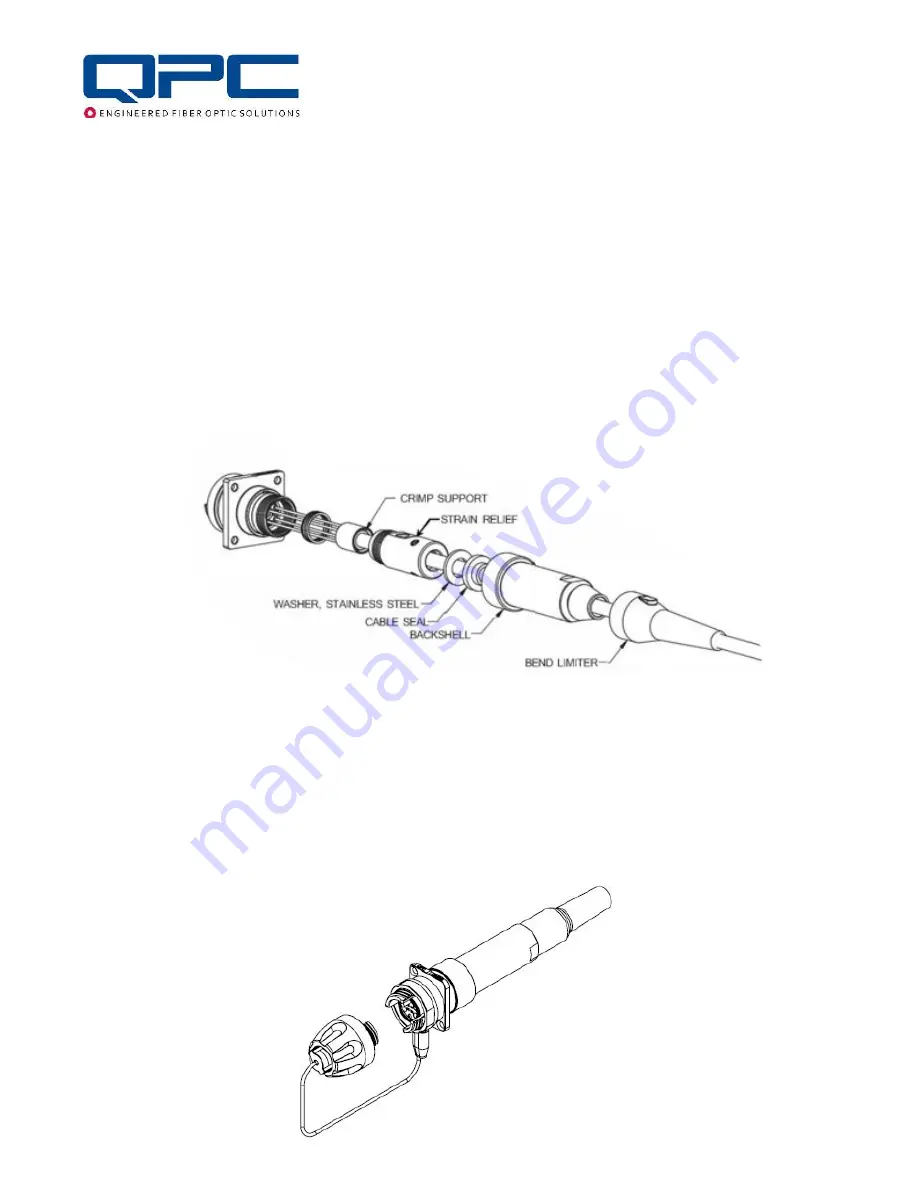
Slide the Wave Spring and Strain Relief into place. Hand tighten the Strain Relief. Check the fiber
through the holes in the Strain Relief to make sure they are not twisted or kinked.
Place assembly in the 4" Drill Press Vise with 2 x Machined Plastic Jaws with Groove PT-591 and use
the Crow’s Foot Wrench PT-536 with the Dial Torque Measuring Wrench PT-506 to torque the Strain
Relief to the values in the above Torque Table. Use Cable to pull Crimp to bottom of Strain Relief. Use
the Hex Driver PT-501 to tighten the Set Screws on the strain relief to lock the crimp into place. Torque
the Set Screws using Torque-Measuring Hex Drive PT-590 and Hex Bit 1/16-inch PT-599 to the values
in the above Torque Table.
Perform a final visual check by looking through the holes of the Strain Relief to make sure that the fiber
is not twisted or kinked. Slide the Washer and the Cable Seal to the base of the Strain Relief. Slide the
Backshell into position and hand-tighten it. Torque the Backshell using the Crow’s Foot Wrench PT-536
with the Dial Torque Measuring Wrench PT-506 to the values in the above Torque Table. Slide the
bend limiter into position and snap into place.
BACKSHELL (7.6mm – 9.5mm Cable Option)
Follow prior instructions labeled “BACKSHELL (4.5mm – 7.5mm Cable Option)”.
For Heat Shrink Bend Limiter Installation
Apply an adhesive (Loctite Stik’N Seal Outdoor Adhesive or similar for rubber applications) on the
inside of the Heat Shrink Bend Limiter. Slide it up towards the base of the Backshell and activate the
heat shrink.


