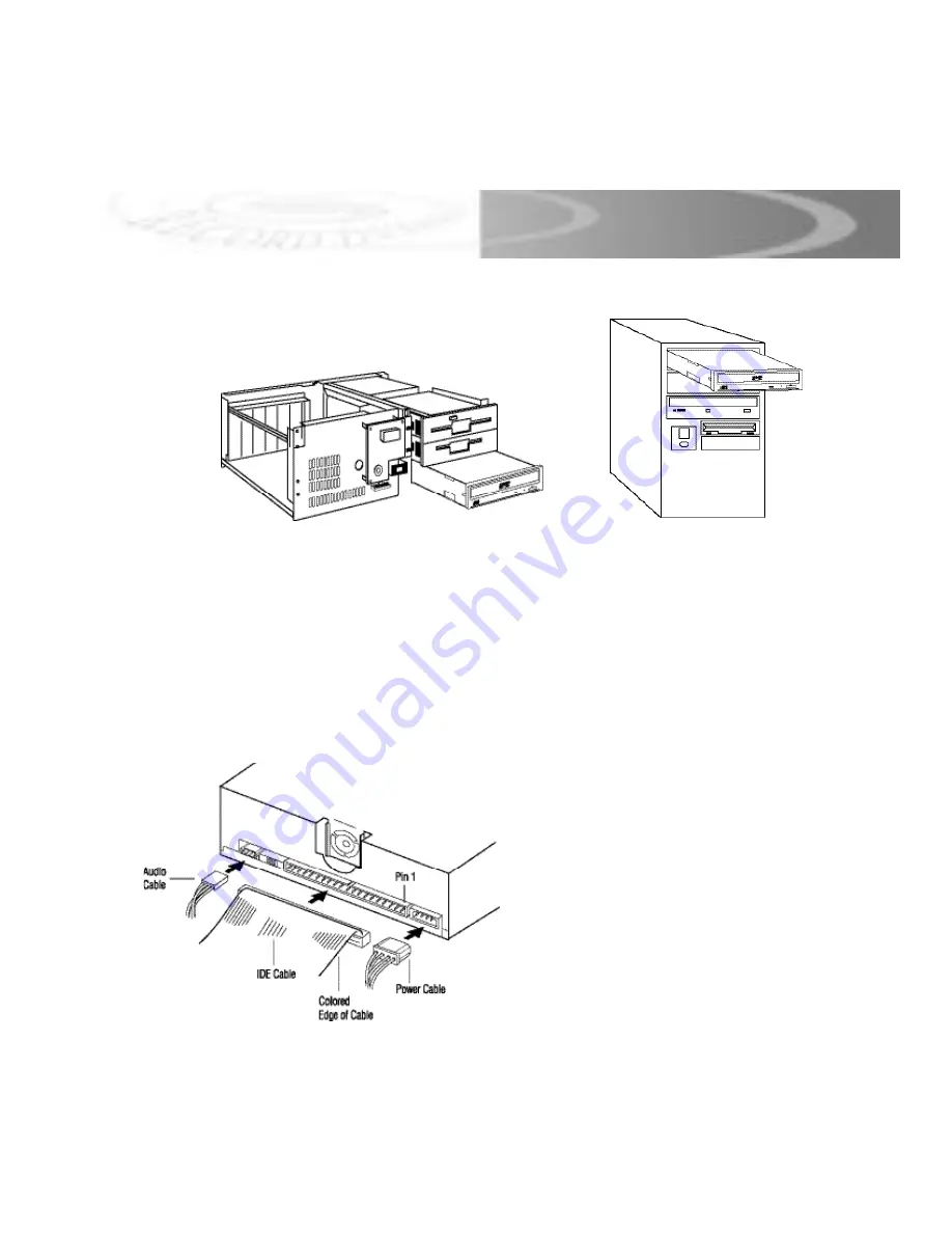
background image

Step 7.

Insert your Que! Drive into the available bay.

Note: 

The Que! Drive must be mounted in a HORIZONTAL position. 

Step 8. 

Put the mounting screws in just tight enough to hold the drive in the system 
but loose enough to be able to move the drive back and forth. 

Step 9. 

Insert the power connection to the back of the Que! Drive. Then plug in the 
IDE ribbon cable to the IDE interface on the back of the drive. Please be sure 
that the side of the IDE ribbon cable with the red stripe goes toward pin 1 on 
the back of the drive. Pin 1 is always marked on the back of internal drives.

Note: Please refer to Que! Internal DVDBurner
Installation Manual CD for complete installation
v e r s i o n .

7

IDE INSTA L L AT I O N

Note: A fan may or may not be present
on your drive. Individual drive
specifications may differ from that
which is show here and may change
without notice.

Summary of Contents for Que!

Page 1: ......

Page 2: ...ny means for any purpose without the prior written permission of QPS Inc Windows is a trademark of Microsoft Corporation Apple Mac OS are trademarks of Apple Computer Inc All other brand and product n...

Page 3: ...atulations on your purchase of the Que Internal DVDBurner Drive In this manual you ll find information designed to help you understand the capability of your new drive as well as a step by step explan...

Page 4: ...z processor 1 1 GHz processor required for real time performance MS Windows 98SE ME 2000 NT 4 0 SP5 128 MB RAM 256 MB recommended CD ROM drive for software install 300 MB free hard disk space for soft...

Page 5: ...3 PACKAGE LIST Drive Software Disc Media Quick Start Guide Ribbon Cable 40 pin IDE cable Audio Cable...

Page 6: ...ls and indicator for the Que Drive for IDE ATAPI Note The front panel may vary slightly Note The location of jumpers may vary from one model to another Note Please refer to Que DVDBurner Installation...

Page 7: ...e the drive that you want to replace Set aside any mounting hardware for later use If your system requires mounting rails go to step 5 otherwise proceed to Step 6 Step 5 Attach the drive mounting hard...

Page 8: ...d designate the first device as the Master and the second device as the Slave This is done by placing the jumpers over the corresponding pins on the back of your DVDBurner drive Note The location of j...

Page 9: ...hen plug in the IDE ribbon cable to the IDE interface on the back of the drive Please be sure that the side of the IDE ribbon cable with the red stripe goes toward pin 1 on the back of the drive Pin 1...

Page 10: ...s up with the pin labeled R If you do not see a connector that matches the audio cable that has been provided in this kit you may need to purchase a special connector for your sound card Step 11 Line...

Page 11: ...ay has fully extended place the disc or DVD RAM cartridge into the center of the tray Press the eject button to have the drive accept the DVD R media or DVD RAM cartridge Note Please refer to Que DVDB...

Page 12: ...press the EJECT button NOTE Some software prohibits the use of the EJECT button so a disc can not be ejected in this way Please refer to the instructions supplied with your software Step 5 Once it ha...

Page 13: ...lens cleaner a lint free cloth or use compressed air Wipe the disc from the center to the outer edge NEVER wipe the disc in a circular motion Always record in a dust free environment If the disc is to...

Page 14: ...12 NOTES...

Page 15: ...NOTES...

Page 16: ...Customer Use Enter below the Model Number and Serial Number which are located either on the rear bottom or side of the unit Model No _____________________ Serial No _____________________ Appearance an...

Reviews: