5
The order of construction is not important. However, a good principle to follow is to install the smaller
components first, so that the larger ones do not prevent easy access.
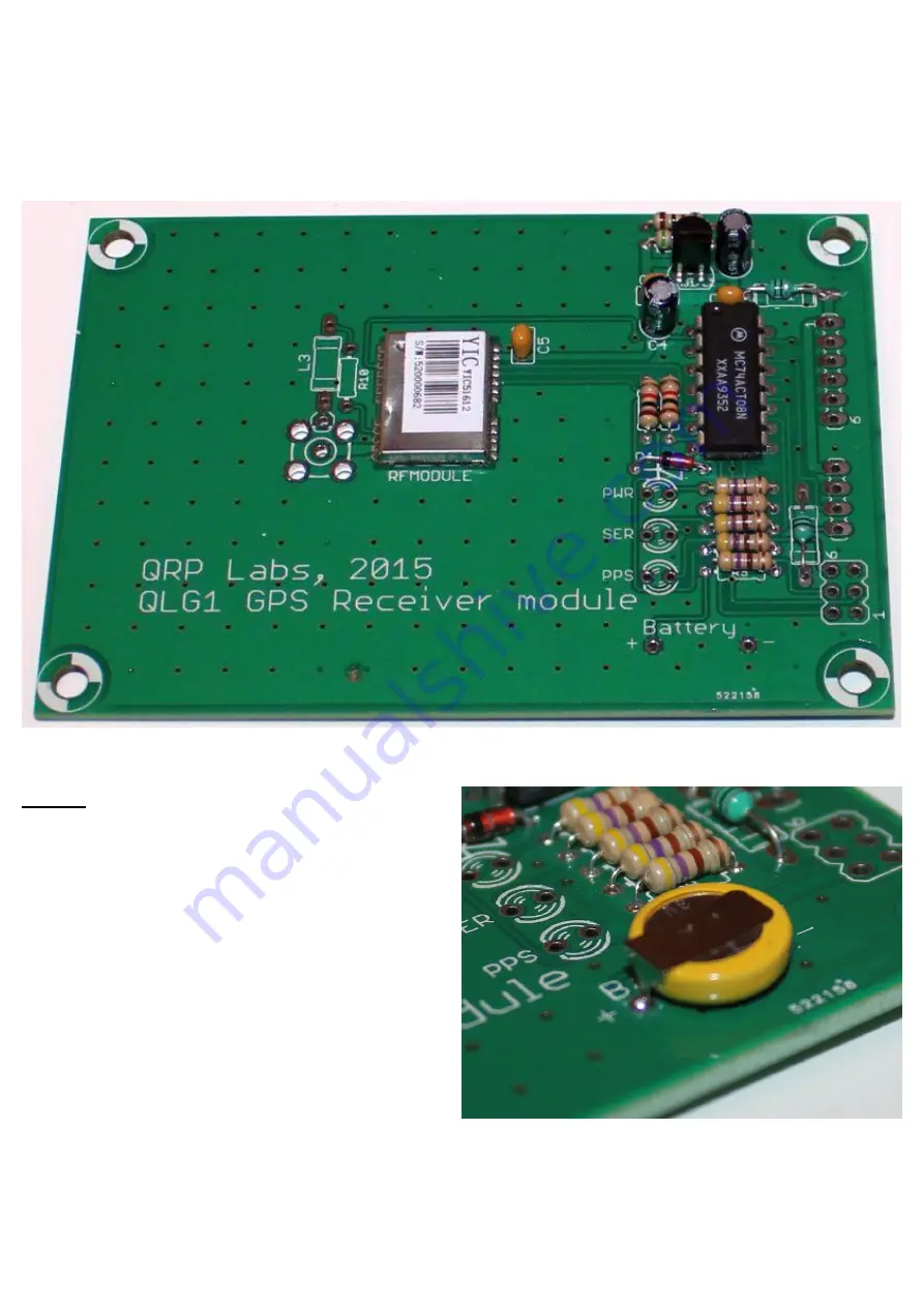
In the following photograph, all the resistors, capacitors, inductors, LM317LZ voltage regulator (3-pin TO92
package), 74ACT08 chip, and 3.6V zener diode have been fitted. Be careful to ensure the correct
orientation of the semiconductors (IC1, IC2, zener diode); also the electrolytic capacitors C3 and C4. The
silk-screen legend on the PCB may be too small to read, so please refer to the parts placement diagram.
Battery
Correct orientation of the battery is particularly
critical! Since the battery will already hold some
charge when it arrives, you must ensure that it is
NOT inserted into the PCB in the wrong way, even
temporarily
– since it would supply reverse power
to the RF module and potentially damage it.
The 3V rechargeable battery has two pins, that fit
the holes on the board. The TOP of the battery, is
the positive connection. This pin fits the hole
labelled “+”. Please study the photograph to the
right, showing the battery correctly installed on the
board.
When soldering the battery, please make it quick. Hot Lithium probably is not a good idea.


