9
Connecting LEDs off-board
The LEDs can also be connected off-board, you may wish to do this if you
are considering boxing the QLG1, and want to still see the status LEDs, for
example on a front panel.
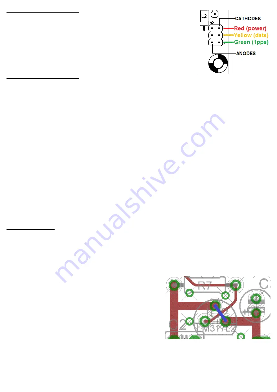
The PCB has a 2 x 3 connector pad at the bottom right (component side)
as in this diagram (right). Each pair of 2 connections is for one LED, as
shown. The cathodes are the pads nearest the board edge.
LED indication in operation
RED
The red power LED will always be lit, when power is applied to the QLG1 board.
YELLOW
The data LED pulses in time with the serial data burst
GREEN
The green 1pps LED will flash once per second, for a duration of 0.1 seconds
Note that the green LED will not flash (indicating 1pps signal) until the module has received sufficient
satellites to compute a position fix solution. This can take some time, particularly the first time the unit is
powered up. Initial acquisition of a satellite requires higher Signal to Noise Ratio (SNR) than tracking.
Once acquired, the satellites orbital characteristics are stored, so that subsequent tracking is possible at
the lower SNR, as soon as the satellite comes into view. Download of all the satellite orbital data in the
constellation can take around 1 hour. So it is quite normal for performance of a GPS module to improve
during the first hour after power up (in terms of number of tracked satellites etc).
Until all the satellites are received the yellow data LED may pulse somewhat erratically, not necessarily
producing one data burst per second.
Once the fix is computed, the 1pps signal is enabled. The green LED will flash for 0.1 seconds, starting
with the commencement of each second. The data burst is initiated at the end of the 0.1 second pulse, and
lasts for perhaps 0.5 seconds (varies depending on data payload).
Default Baud Rate
The default baud rate of the QLG1 is 9,600 baud. This is compatible with the default settings of the
Ultimate3S QRSS/WSPR TX kit (and other QRP Labs products). The list of default NMEA sentences is
described in a later section. The RF module (Mediatek chipset) can also accept serial commands that
change its baud rate and the NMEA sentences in the serial data burst. This is beyond the scope of this
document.
Powering from 3.3V
The QLG1 GPS Receiver module can also be powered at
3.3V if desired. In this case, simply do not install the LM317LZ
voltage regulator, and you may also omit R6 and R7. Instead,
install a wire link as shown (right), to bypass this voltage
regulator.
When powering with 3.3V, the TXD and 1pps output signals
will also have 3.3V levels.


