3
Example:
This core counts 6 Turns
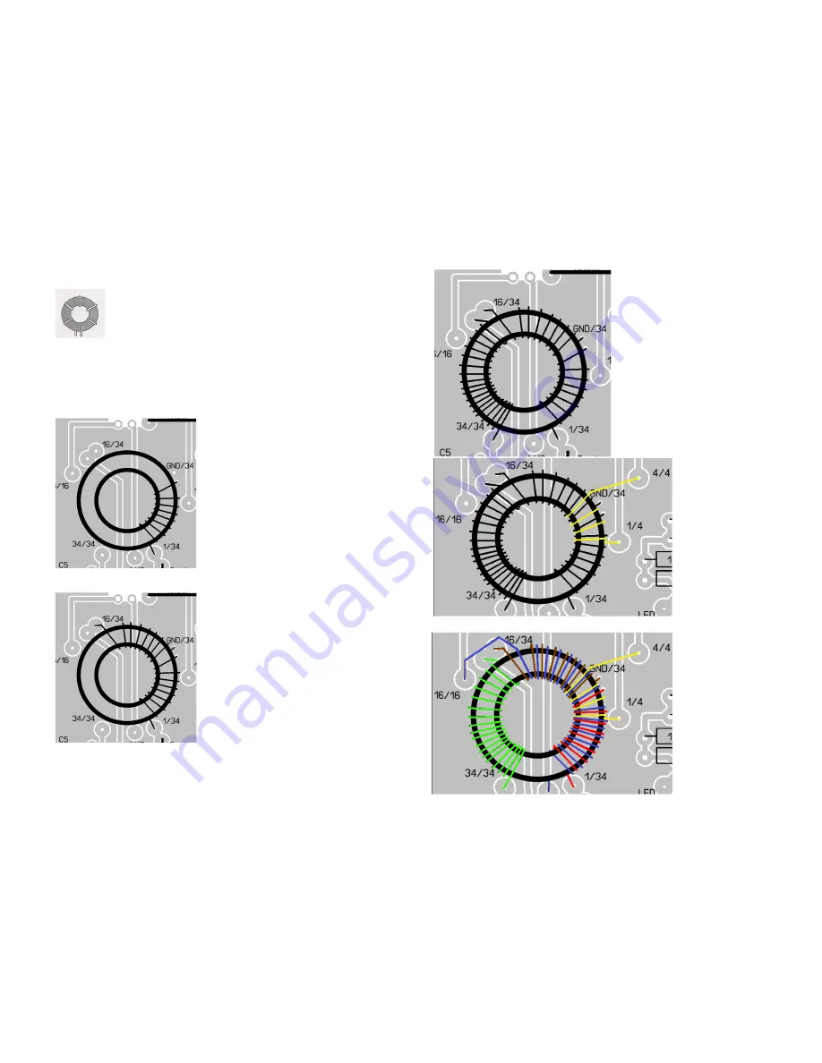
The ZM4 main Torroit needs 1 main winding (the resonate winding)
with 2. taps plus two different coupling windigs for the low and high impedance
outputs. To make it easier to difference them we use coloured wires. Start wit the
red wire. Put it from the backside of the core through the core, tis is the first turn. A
short end (abt 2-3cm of the wire remains at the beack side, the longer end is in front
of you. Feed the long end around the core to the
back and again from back to front through the coer
which gives the second turn (remember, count
inside the core). The long end of wire must be
RIGHT side of the first turn now. Pull the long wire
tight to the core body. Now wind the remaining 6
turns of the first winding (complete part 1 is 8 turns
INSIDE)
Later on the 8 Windings will be soldered to the
PCB. They are the first part of the main winding
which has a total of 34. The PCB is marked with
1/34 which means 1 of 34 at the beginning and
GND/34 which means Ground of 34. Lay the
Torroid on the PCB and cut the wire at both ends.
Leave the ends long enough to fit them through
the holes named 1/34 and GND/34. Remove the
insolation but do not solder yet.
The next part of the 34 turn winding of course
must start where the first part ends. So that is the
reason to have two holes in the PCB here. Use
the brown wire and wind the next 8 turns following
the same way: From back to front, new turn
allways right side of old turn.
Count 8 turns and cut and remove insulation so
the ends fit into hole GND/34 and 16/34 (16 of 34)
Now the remaining part of the main winding. This
are 18 turns. They start at the second hole of
16/34 and end at 34/34.
Use green wire, count inside, shorten the wires
and remove the insilation at both ends to make
them fit into the PCB holes. Do not solder yet, you must wind the couplings first.
Let´s start with the shorter coupling
winding. It contains of 4 turns. The
coupling must be as symmetrical around
the ground point of the main winding as
possible. Remember, grounding point is
named GND, actually it is the connection
between the red and the brown wire.
Symmetrically means, the ground point
must be exactly in the middle of the
four coupling turns, two before and two
behind.
Use the yello wire and wind two turns
between the last 2 of the red and the first
two of the brown wire.
Pay attention to the fact the the holes
for the coupling at the PCB are a little
bit away from the torroid,
so do not shorten the wire
ends too short.
So, we are not far away
from our goal, it is only the
longer coupling winding
missing.
Use the blue wire to make
it. This one also must be
symmetrical around the
ground point so we need
8 turns before and 8 turns
after the ground point. Start
left of the red number one
and wind again from back
to front. every blue turn
is laying between two red
turns. Turn number 7 and
8 just before you come
to ground point must lay
between the red and the
yellow wire. Yes, there is
not to much space left,
but you will see they fit
all together. Behind the
ground point wind the
remaining 8 turns.
Summary of Contents for ZM-4
Page 8: ...8...


