4
If you are ready, shorten the ends corresponding to the holes and remove the
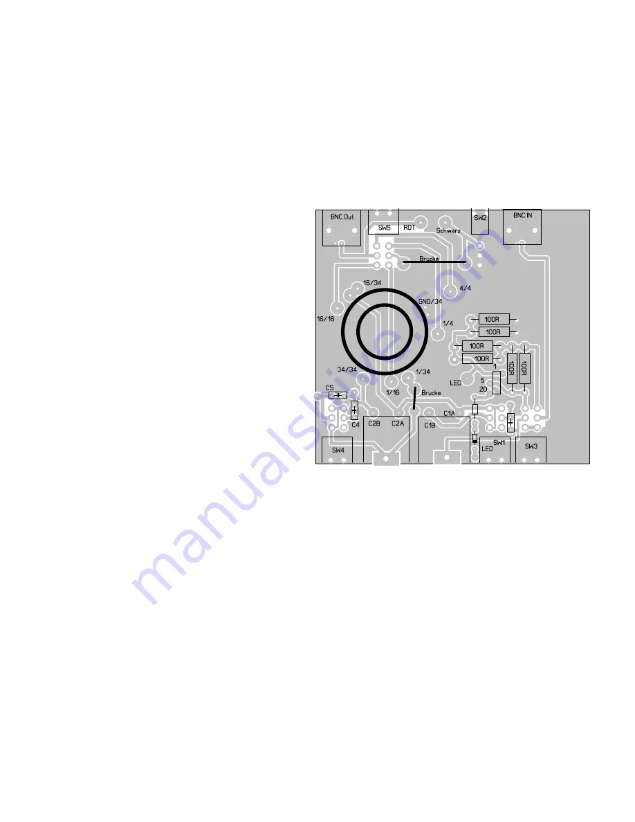
isolation at both ends. Now put the complete torroid to the PCB and fit all wire ends
in the corresponding holes. Tighten the ends, they should hold the Torroid flat on
the PCB. Bend them at the solder side of the PCB abt 45 degrees to old them in
place until you solder them.
Take care to use the correct holes for all wires!!
Start blue = 1/16
Start red = 1/34
Start yellow = 1/4
End red = Gnd/34
Start brown = Gnd/34
End yellow = 4/4
End brown = 16/34
Start green = 16/34
End blue = 16/16
End green = 34/34
To hold the Torroid really flat to the PCB it´s good practise to tighten the wire ends
sequential several times. Go arrouund from wire to wire until al wire ends ar tight. If
the Torroid is placed as it should be, solder all wire ends.
Next place all low profile parts. Start with the two wire jumpers marked as „Brucke „
at the PCB (thats the German name for „bridge“) Use two pieces of wire.
[ ] Short jumper at 1/34
[ ] long Jumper above 4/4
Now the „fat“ Resistors. This are 100Ohm resistors because by using 2 of them
parallel we also have 50 Ohm but less heat problems when tuning with full gallon
QRP.
[ ] 100R pair 1
[ ] 100R pair 2
[ ] 100R Pair 3
Go on with the caps. For all caps there is a second hole in the PCB. They are only
used if we use caps with bigger spacing. For all caps with 2,5mm spacing use the
holes inside the silk screen printing
[ ] C5 lower left side 220pF
[ ] C4 lower left side 270pF
[ ] C3 lower right side 390pF (Missing marker C3, only the Cap symbol on the PCB)
Now place and solder
[ ] 1 kOhm Resistore left C3 above the Diode marker
[ ] Diode 1N4148, The black band must be placed to the side marked with a band
on the BCB
Now the other torroid. This one is much smaller the the main torroid. It´s a gray
ferrite FT37-43. We need a total of 25 turns tapped at 5 turns.
Start by winding 5 turns. After 5 turns leave abt 2-3cm, twist them together, this
gives you the tap. Now the remaining 20 turns.
Because the 0,2mm wire we use for this torroid is insulated by laquer, you must
destroy the laquer before you can solder the wire ends to the PCB. If you are not
famliar with this technique, again look to the good description written by Papa Diz at
http://kitsandparts.com/wtoroids.html.
Now place the torroid to the PCB. The start turn (the shorter end to the tap) goes to
Summary of Contents for ZM-4
Page 8: ...8...


