●
Trimmer capacitor CT 7 – Green trimmer. Make sure the flat side of the part is facing the line drawn in the circle
outline on the board.
Transistors:
Be sure to properly ready the part number on the three legged transistors so they go in the proper place. A magnifying
glass maybe helpful for this. When installing the part, look out of thin shavings of the plating on the leads which might
come off as you push the legs into the holes. These can cause shorts between the leads. Space the package about 1/8”
above the board – no not push real close to the board. Also, be sure to orientate the flat side of the package with the flat
side of the part outline. Note that the leads of some the parts will have to be reformed to match the pad pattern on the
board.
□ Install Q2, Q3, Q4 – BS170 mosfets – these are static sensitive!
□ Install Q1, Q6, Q8 – 2N7000 mosfets – these are also static sensitive.
□ Install Q9 – 2N3904 NPN
□ Install Q5 – 2N3819 j-fet
□ Install Q7 – J-176 j-fet
□ Install U5/U10 – 78L05 5V regulator
□ Install Q10, FQPF27P06 or FQPF11P06 – bend leads 90 degrees to body and mount flush to board.
●
Now install all the Electrolytic capacitors. Be sure to observe proper polarity. Long lead is plus side. Black stripe on
the body of the can indicates negative side. C1 can explode if installed backwards!
□ C1 - 220 ufd /16V
□ C41, C69 3.3 ufd /16V
□ C53, C61 10 ufd /16V
□ C66, C70 47 ufd /16V
●
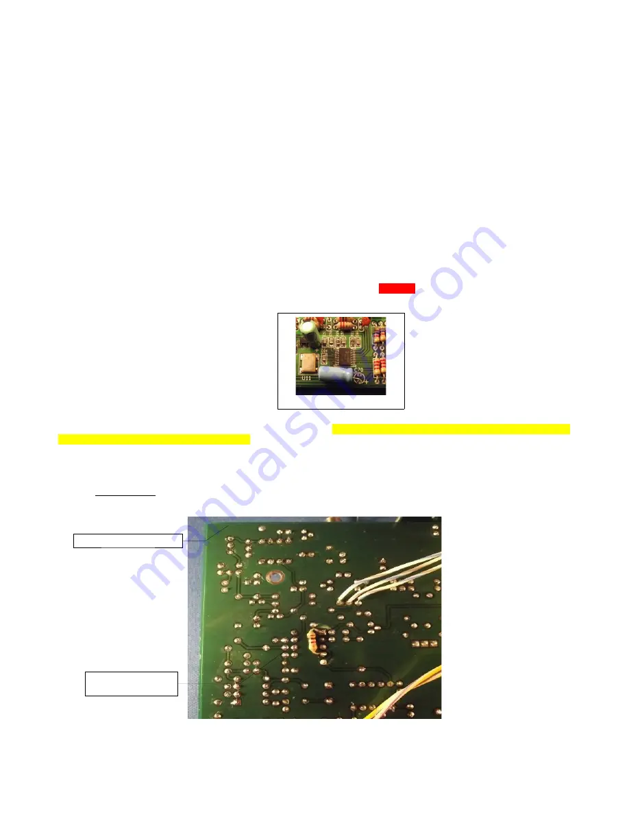
NOTE: install C70 laying on it's side.
●
DC power jack and relays.
□ Install DC power jack
□ Install the four (4) relays, RLY1, RLY2, RYL3 and RYL4. Note the line on one end of the relay and match this with
the line on the board relay outline. Be sure to double check before soldering. If you get it in backwards, it's real
hard to remove.
●
Wind L7 – 10 turns #28 magnet wire on FT37-43 core (black) Do not install at this time, put aside for use later
after initial board testing.
●
Modification:
a 1K resistor is added to the bottom of the board, connected to pins 1 and 4 of U3. While not
required for operation, it does reduce distortion on the output of the op-amp for large signals and improves the
quality of the audio.
13
C70 mounting
Add 1 K between
pins 1 and 4 of U3.
Front, left side of board.
Summary of Contents for KD1JV
Page 8: ...Ink jet friendly diagram 8 ...
Page 9: ...9 ...
Page 17: ...Assembled board wired into case Note how wires float above the board 17 ...
Page 21: ...Schematics 21 ...
Page 22: ...22 ...


