background image

Band specific parts:

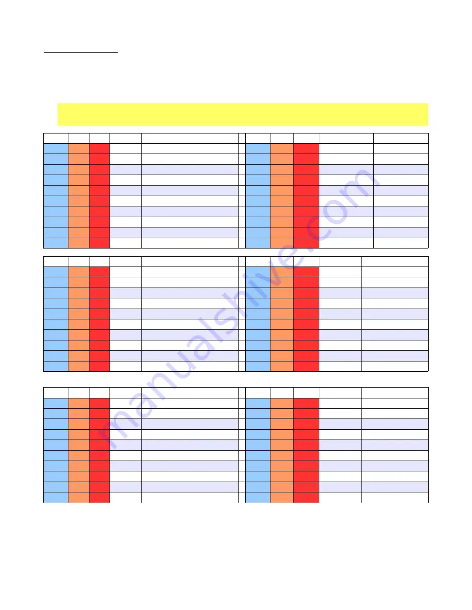
Part locations are listed in table for band A, then band B and then Band C. The lowest frequency band should be made band A and the 
highest frequency band C. For example, band A could be 80 meters, while band C would be 15 meters, but not the other way around. This 
ensures the highest frequency band has the shortest track lengths. 

On the color parts layout, band A parts are shown highlighted in light Blue, band B parts in Orange and band C parts in Red.

Be sure to count the turns on the low pass filter coils, L8 through L13 correctly. Each time the wire passes through the center of the 
core, this is one turn. Having one extra turn, which is a common mistake, will result in reduced power output. Also the turns should 
be reasonably tight to the core. Sloppy winding can result in reduced performance.  Evenly space the turns around the core. 

80

Value

Type

40

Value 

Type

A

Will always be band A 

A

B

C

C12

100 pfd 

101 NPO Disk

C12  

C11

C10

68 pfd

NPO disk

C3

680 pfd

681 mono C0G

C3, 

 C8

C7

330 pfd (331)

C0G

C21

1500 pfd

152 mono C0G

C21 

 C16

C20

680 pfd (681)

C0G

C26

680 pfd

681 mono C0G

C26

C25

 C24

330 pfd (331)

C0G

C19

15 pfd

15 NPO Disk

C19 

C18

C6

10 pfd 

NPO disk

CT5/6

70 pfd

Brown trimmer

CT5/6 

CT3/4

CT1/2

70 pfd trimmer

Brown

L12

24 turns 

#30 wire T37-2 Red

L12

 L10

L8

18 turns

#28 wire T37-2 Red

L13

29 turns

#30 wire T37-2 Red

L13

 L11

 L9

20 turns

#28 wire T37-2 Red

L5/6

39 uHy

ORG/WHT/BLK/GLD

L5/6

 L3/4

 L1/2

12 uHy

BRN/RED/BLK/GLD

30

Value

Type

20

Value 

Type

A

B

C

A

B

C

C12

C11

C10

47 pfd 

47 NPO Disk

C12  

C11

C10

22 pfd

22 NPO Disk

C3

C8

C7

220 pfd

221 mono C0G

C3, 

 C8

C7

150

151 mono C0G

C21

C16

C20

560 pfd 

561 mono C0G

C21 

 C16

C20

330

331 mono C0G

C26

C25

C24

220 pfd

221 mono C0G

C26

C25

 C24

150

151 mono C0G

C19

C18

C6

4.7 pfd 

4.7 NPO Disk

C19 

C18

C6

2.2 pfd 

2.2 NPO Disk

CT5/6

CT3/4

CT1/2

30 pfd 

Green trimmer

CT5/6 

CT3/4

CT1/2

30 pfd

Green trimmer

L12

L10

L8

13 turns

#28 wire T37-2 Red

L12

 L10

L8

13 turns

# 28 wire T37-6 Yellow

L13

L11

L9

17 turns

#28 wire T37-2 Red

L13

 L11

 L9

16 turns

#28 wire T37-6 Yellow

L5/6

L3/4

L1/2

8.2 uHy

GRY/RED/GLD/GLD

L5/6

 L3/4

 L1/2

5.6 uHy

GRN/BLU/GLD/GLD

17

Value

Type

15

Value 

Type

A

B

C

A

B

C

C12

C11

C10

15 pfd 

15 NPO disk

C12  

C11

C10

15 pfd 

15 NPO disk

C3

C8

C7

47 pfd

47 mono C0G

C3, 

 C8

C7

47 pfd

47 mono C0G

C21

C16

C20

220 pfd 

221 mono C0G

C21 

 C16

C20

220 pfd 

221 mono C0G

C26

C25

C24

100 pfd 

101 mono C0G

C26

C25

 C24

100 pfd 

101 mono C0G

C19

C18

C6

2.2 pdf

2.2 NPO Disk

C19 

C18

C6

2.2 pfd

2.2 NPO Disk

CT5/6

CT3/4

CT1/2

30 pfd 

Green trimmer

CT5/6 

CT3/4

CT1/2

30 pfd 

Green trimmer

L12

L10

L8

13 turns 

# 28 wire T37-6 Yellow

L12

 L10

L8

11 turns 

#28 wire T37-6 yellow

L13

L11

L9

16 turns 

# 28 wire T37-6 Yellow

L13

 L11

 L9

14 turns

#28 wire T37-6 yellow

L5/6

L3/4

L1/2

3.3 uHy

ORG/ORG/GLD/GLD

L5/6

 L3/4

 L1/2

3.3 uHy

ORG/ORG/GLD/GLD

14

Summary of Contents for KD1JV

Page 1: ... 15 meters choose band mix at time of order 5 watts output on all bands with 13 8V supply Built in Iambic keyer with 5 to 40 wpm code speed selectable Iambic A or B modes and two 63 character message memories Receiver sensitivity 0 2 uV MSD DDS VFO for rock steady stability with 50 Hz and 200 Hz tuning rates Easy to read four digit LED display with leading zero suppression Rotary knob tuning RIT r...

Page 2: ...9 kHz from the transmit frequency When RIT is activated the display will change to show the difference between the current transmit frequency and the new receive frequency Normally RIT is used to fine tune in a station which is not quite on your frequency but can also be used when a DX or contest station is operating Split and listening off their transmit frequency When RIT is active it is possibl...

Page 3: ...via the paddle Letter and word spaces are automatically inserted when the applicable pause is detected The pause length is the ideal spacing of 3 dots for a letter and 7 dots for a word Since many people don t pause long enough between letters and words in normal on air sending the best way to insure a space is inserted is to pause a little longer than your used to for letters and much longer for ...

Page 4: ...addle When done exit back to normal operation by clicking the MENU switch again Speaker or headphones There is sufficient audio output power to drive a small 8 ohm speaker Care should be taken when using headphones to keep the volume turned now when tuning around the band Although the audio AGC action will limit the volume of strong stations this can still be too much when using headphones Power s...

Page 5: ... work against if the volume control is turned all the way up As the audio output level of U8 starts to exceed 400 mv Q9 starts to turn on reducing the voltage at Q7 s gate and thereby starting to turn Q7 on and attenuate the input signal to the amplifier The gate voltage of Q7 will find a level at which it will keep the output voltage of U8 at 400 mv peak C41 at Q7 s gate holds the AGC voltage ste...

Page 6: ...BRN BLK BLK GLD RFC 1 14 pin DIP socket 1 30 pfd Green trimmer cap 1 28 pin DIP socket 0 3 width 3 22 pfd 22 NPO disk 5 4 91520 MHz HU 49US crystal matched 1 47 pfd 47 NPO disk 1 FT37 43 Black ferrite toroid core 8 100 pfd 101 NPO disk 1 2 5 mm Power Jack PC mount 2 470 pfd 471 disk 1 6 mm x 13 mm TACK switch 7 0 001 uFd 102 disk 1 16 pin right angle SIP pin strip 3 0 01 uFd 103 Film 1 Rotary Enco...

Page 7: ...e For example instead of saying you need R22 say you need a 1K resistor Otherwise we will have to look up the parts list for the kit and figure out what R22 is and that can delay getting you that part In general parts are numbered on the board in rows starting with the lowest part number in the upper left corner of the board this is the back end and then run left to right and then zig zag down the...

Page 8: ...Ink jet friendly diagram 8 ...

Page 9: ...9 ...

Page 10: ...aluminum chassis is difficult due to the brushed surface so we advise pre coating the chassis with the Krylon clear before applying the decals Unless you have elected to paint the chassis first 1 Trim around the decal 2 After trimming place the decal in a bowl of lukewarm water with a small drop of dish soap to reduce the surface tension for 10 15 seconds 3 Using tweezers handle carefully to avoid...

Page 11: ... 2 2 K RED RED RED GLD R44 1K BRN BLK RED GLD Molded inductors There are four 4 molded inductors RFC to install These look like resistors but are a little shorter and fatter Like resistors the value is also color coded on the body of the part Install L15 L16 3 3 uhy ORG ORG GLD GLD Install L14 L17 10 uhy BRN BLK BLK GLD Diodes Be sure to observe proper polarity Band near end of part goes towards l...

Page 12: ... pfd cap and not a 470 pfd cap A 470 pfd cap would be marked 471 Mono caps also often have letters printed on the part These letters indicate the type or tolerance and can be disregarded NOTE Electrolytic band specific values will be installed later and pre installed SMT caps are not listed in table below location value type location value type C2 0 1 ufd 104 MONO YELLOW C37 0 01 ufd 103 FILM GREE...

Page 13: ... 78L05 5V regulator Install Q10 FQPF27P06 or FQPF11P06 bend leads 90 degrees to body and mount flush to board Now install all the Electrolytic capacitors Be sure to observe proper polarity Long lead is plus side Black stripe on the body of the can indicates negative side C1 can explode if installed backwards C1 220 ufd 16V C41 C69 3 3 ufd 16V C53 C61 10 ufd 16V C66 C70 47 ufd 16V NOTE install C70 ...

Page 14: ...wire T37 2 Red L13 29 turns 30 wire T37 2 Red L13 L11 L9 20 turns 28 wire T37 2 Red L5 6 39 uHy ORG WHT BLK GLD L5 6 L3 4 L1 2 12 uHy BRN RED BLK GLD 30 Value Type 20 Value Type A B C A B C C12 C11 C10 47 pfd 47 NPO Disk C12 C11 C10 22 pfd 22 NPO Disk C3 C8 C7 220 pfd 221 mono C0G C3 C8 C7 150 151 mono C0G C21 C16 C20 560 pfd 561 mono C0G C21 C16 C20 330 331 mono C0G C26 C25 C24 220 pfd 221 mono C...

Page 15: ...ay NOTE Clip leads along bottom side of switch just above the holes for the SIP pins flush to the board and solder pins from front side of board Encoder Mating Front panel board to Main board 1 Insert long leads of SIP pin strip up through bottom side of main board Make sure it is seated against the board along it s length 2 Solder pins and clip off excess pin length 3 Attach front panel board to ...

Page 16: ...tion of the case by angling it in making sure the shaft for the tuning encoder and Keyer PSB switch are lined up with their respective holes In addition the Band select switch and volume control will need to lined up and inserted into their mounting holes before the board can be fully inserted into the cabinet bottom Once the board is in place the headphone paddle and antenna jacks can be installe...

Page 17: ...Assembled board wired into case Note how wires float above the board 17 ...

Page 18: ...g closed the DASH paddle and the KEYER switch while turning power to the rig on The keyer will now be operational and you can send some Morse Receiver testing and BFO adjustment 1 Disconnect power from rig 2 Insert SA162A chips into U1 and U2 sockets 3 Insert LM358 into U3 socket 4 Insert LM386 into U8 socket Hold closed the DOT paddle and KEYER switch while turning power to the rig on The rig wil...

Page 19: ... volt supply the power output should be about 5 watts Power output can be tweaked to some extent by changing the spacing of the turns on the low pass filter cores With a little experimentation it should be possible to achieve 5 watts output on each band Coils L8 L10 and L12 will have the most effect on power output These are the inductors which follow the PA FETS and influence the matching between...

Page 20: ... paddle or hear hiss when the volume control is turned all the way up the audio amp is working If there is no side tone or hiss the problem maybe a simple as the wiring to the speaker headphone jack or you may have forgotten to install the two SIP pins to the left of the main row of pins If missing pins is the problem use resistor lead clippings to make the connections as unsoldering the main row ...

Page 21: ...Schematics 21 ...

Page 22: ...22 ...

Reviews: