14
Trouble shooting guide:
In most cases, any problems with the getting the rig to work will be tracked down to soldering problems or miss placed parts. A close visual
inspection of the board is often enough to find soldering problems or the miss-placed parts.
Soldering problems fall into four groups:
1.
Missing solder connections
2.
Solder bridges between closely spaced pads which should not be connected togther.
3.
Solder which stuck to the part lead but did not flow into the solder pad on the board. This is often caused by not using enough
heat or not placing the iron tip on both the lead and the solder pad.
4.
Not making connection to the wires on the toroid coils. Even if you pre-tined the magnet wire, you may have pulled it past the
tinning when inserting the wires into the board and are not making a connection. Buzz out the connection to ensure
continuity.
Miss-placed parts:
The most common error here is not reading the resistor color code correctly. Some values have identical colors, but in a different order. It is
easy to mistake a 51 ohm resistor (Green/Brown/Black) for a 1 Meg resistor (Brown/Black/Green)
Trouble shooting technique:
The trick to trouble shooting is being able to narrow down the area to look at to find the problem. Just using a DVM will be sufficient for basic
trouble shooting. For more difficult cases, an Oscilloscope and signal generator may be needed to track signals through the circuits.
In any case, one should first determine which parts of the circuit are working properly and this will lead you to what is not. If the rig is
completely dead, the problem is likely with the power supply and could very well be a short to ground somewhere on the 5 volt supply
feeding most of the IC's. If the display comes on, the microprocessor is working and if you get side tone when you use the paddle, or hear
hiss when the volume control is turned all the way up, the audio amp is working. If there is no side tone or hiss, the problem maybe a simple
as the wiring to the speaker/headphone jack or it might in the audio amp area.
If you get audio, but can not hear any off air signals, the problem is more difficult to find as it could be anywhere between the antenna jack
and the audio amp. In this case having a signal generator and Oscilloscope are of great help in tracing the signal though the circuits.
Transmitter:
There is not a whole lot which can go wrong with the transmitter portion. Check for PA keying voltage coming out of Q10, proper soldering of
the toroid magnet wire.
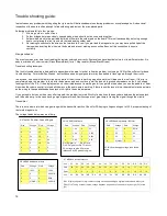
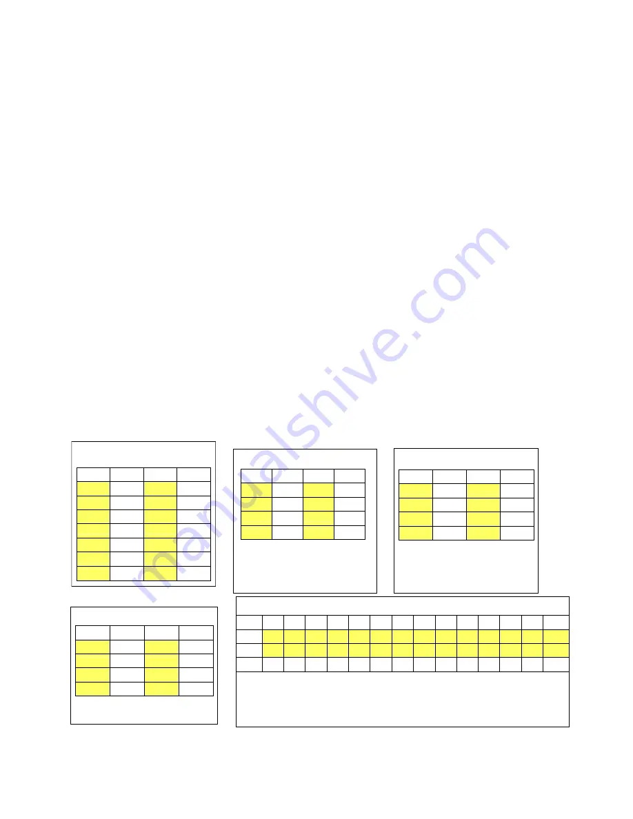
The voltage tables below may be of help.
U7 MEGA48 Microprocessor
Volt
5V
5V
5V
0V
5V
0V
0V
5V
5V
5V
5V
DS
5/0
5/0
Pin#
28
27
26
25
24
23
22
21
20
19
18
17
16
15
Pin#1
2
3
4
5
6
7
8
9
10
11
12
13
14
Volt
0V
DS
DS
DS
DS
DS
5V
0V
DS
DS
DS
DS
DS
DS
DS = Display segment or digit select voltage varies depending on digits displayed and duty cycle.
Pins 15/16 Tuning encoder inputs, voltage depends on position of encoder, may be high (5V) or low
(0V)
U2 74AC02 PA driver, Quad NOR gate
Pin#
Voltage
Pin#
Voltage
1
0
14
5V
2
0
13
0
3
5V
12
0
4
5V
11
5V
5
0
10
5V
6
0
9
0
7
0
8
0
U3/U4 SA612A Mixers
Pin#
Voltage
Pin#
Voltage
1
1.4V
8
5V
2
1.4V
7
4.25V
3
0
6
4.96V
4
3.9V
5
3.9V
Pin1/2 signal in
Pin 6 Osc in
Pin 4/5 signal out Pin 7 Osc out
DC Voltage on pins 6/7 maybe
influenced by RF present on pins.
U6 LM358 audio preamp / BP filter
Pin#
Voltage
Pin#
Voltage
1
5V
8
DCIN
2
5V
7
5V
3
5V
6
5V
4
0 (GND)
5
5V
DCIN = board supply voltage, less diode
drop.
U9 LM386 audio power amp
Pin#
Voltage
Pin#
Voltage
1
1.33V
8
1.34V
2
0
7
1/2 DCIN
3
0
6
DCIN
4
0 (GND)
5
1/2 DCIN


