6
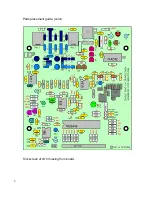
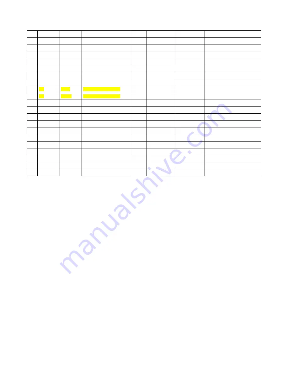
Part by part placement guide:
Resistors
√
location
Value
Color code
√
Location
Value
Color code
R1
100 K
BRN/BLK/YEL/GLD
R21
270
Ω
RED/VOL/BRN/GLD
R2
47 K
YEL/VOL/ORG/GLD
R22
270
Ω
RED/VOL/BRN/GLD
R3
51
Ω
GRN/BRN/BLK/GLD
R23
1 MEG
BRN/BLK/GRN/GLD
R4
100 K
BRN/BLK/YEL/GLD
R24
1 K
BRN/BLK/RED/GLD
R5
270
Ω
RED/VOL/BRN/GLD
R25
2.2 K
RED/RED/RED/GLD
R6
270
Ω
RED/VOL/BRN/GLD
R26
1 MEG
BRN/BLK/GRN/GLD
R7
470
Ω
YEL/VOL/BRN/GLD
R27
1 K
BRN/BLK/RED/GLD
R8
3.9 K
SMT PREINSTALLED
R28
2.2 K
RED/RED/RED/GLD
R9
270
Ω
SMT PREINSTALLED
R29
1 K
BRN/BLK/RED/GLD
R10
270
Ω
RED/VOL/BRN/GLD
R30
2.2 K
RED/RED/RED/GLD
R11
2.2 K
RED/RED/RED/GLD
R31
22 K
RED/RED/ORG/GLD
R12
22 K
RED/RED/ORG/GLD
R32
2.2 K
RED/RED/RED/GLD
R13
220 K
RED/RED/YEL/GLD
R33
2.2 K
RED/RED/RED/GLD
R14
2.2 K
RED/RED/RED/GLD
R34
2.2 K
RED/RED/RED/GLD
R15
470 K
YEL/VOL/YEL/GLD
R35
2.2 K
RED/RED/RED/GLD
R16
10 K
BRN/BLK/ORG/GLD
R36
2.2 K
RED/RED/RED/GLD
R17
1 MEG
BRN/BLK/GRN/GLD
R37
2.2 K
RED/RED/RED/GLD
R18
220 K
RED/RED/YEL/GLD
R38
2.2 K
RED/RED/RED/GLD
R19
470 K
YEL/VOL/YEL/GLD
R39
2.2 K
RED/RED/RED/GLD
R20
10 K
BRN/BLK/ORG/GLD
R40
10
BRN/BLK/BLK/GLD
Molded inductors:
There are four (4) molded inductors (RFC) to install. These look like resistors but are a little shorter and fatter. Like resistors, the value is also
color coded on the body of the part.
•
Install L3/L4 – 3.3 uhy ORN/ORN/GLD/GLD
•
Install L6/L7 – 10 uhy BRN/BLK/BLK/GLD
Diodes: Be sure to observe proper polarity. Band near end of part goes towards line on part outline.
•
Install D1 – 1N5817 large plastic body.
•
Install D2 – 1 N4756A large glass body
•
Install D3/D4/D5 – 1N4148 small glass body
Crystals:
The crystals are now installed, the locations are shown filled in with light gray. All the crystals are matched and the same frequency, so it
doesn't matter which ones go where. The cans of the X1 to X4 crystals should be tack soldered to the solder pad located next the the body
of the crystal. This should be done now, as getting an iron in after the near-by capacitors are installed will be difficult.
•
Install X1 to X5
IC sockets:
IC sockets are now installed. Before soldering, make sure they are flush to the board and that all the pins are sticking out of the holes on the
bottom of the board. If a pin gets bent over as you are inserting the socket, this will be difficult to fix once the other pins have been soldered.
•
U3, U4, U6, U9 – 8 pin socket
•
U2 – 14 pin socket
•
U7 – 28 pin socket


