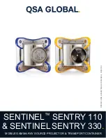
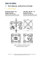
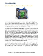
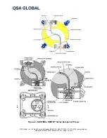
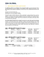
background image


OPERATIONS & MAINTE

NA

NC

E MANU

AL. MAN

-038


SENTINEL

 SENTRY 110 

& SENTINEL


SENTRY 330

.

 MOBILE GAMMA-RAY SOURCE PROJECTOR & TRANSPORT CONTAINER 

Summary of Contents for SENTINEL SENTRY 330

Page 1: ...OPERATIONS MAINTENANCE MANUAL MAN 038 SENTINEL SENTRY 110 SENTINEL SENTRY 330 MOBILE GAMMA RAY SOURCE PROJECTOR TRANSPORT CONTAINER ...

Page 2: ... 4 Daily Inspection of the Gamma Ray Source Projector 31 3 5 Daily Inspection of the Source Guide Tube s 31 3 6 Daily Inspection of the Remote Controls 32 4 QUARTERLY AND ANNUAL MAINTENANCE REQUIREMENTS 37 4 1 Routine Quarterly Maintenance Requirements 38 4 2 Routine Annual Maintenance Requirements 40 4 3 Annual Maintenance for the SENTINEL SENTRY 110 SENTINEL SENTRY 330 Gamma Ray Source Projector...

Page 3: ...tions Manual MAN 038 March 2019 Page 3 of 100 6 DEFINITIONS TERMS 93 7 EMERGENCIES AND PERSONNEL SAFETY 96 7 1 Emergencies 96 7 2 Training 97 7 3 Access to Restricted Areas 97 7 4 United States Regulations 97 7 5 EU Regulations 98 7 6 Personnel Monitoring 98 8 DISPOSAL 99 9 CONTACT INFORMATION 100 ...

Page 4: ...simetry including film badges or thermoluminescent dosimeters optically stimulated luminescence badges OSL direct reading pocket dosimeters and audible alarm ratemeters must be worn during all radiographic operations It is imperative that the users of these containers perform adequate radiation surveys of the gamma ray source projector Surveys must be performed using a calibrated survey instrument...

Page 5: ...1 General Details SENTINEL SENTRY 330 SENTINEL SENTRY 110 Standard Assembly Standard Assembly Cobalt 60 330 Ci 12 TBq Cobalt 60 110 Ci 4 TBq Maximum package weight 780 lbs 354 kg Maximum package weight 605 lbs 274 kg Equipped with yellow handling rib assembly Equipped with blue handling rib assembly Figure 1 SENTRY Series Dimensional Views All dimensions shown are inches ...

Page 6: ... space of the welded housing is filled with polyurethane foam to prevent the ingress of water or foreign material but is open to atmospheric pressure The stainless steel housing containing the DU shield locking mechanism outlet port protective covers and required labels comprise the radioactive material device which also serves as a Type B U transport package The devices include a handling rib ass...

Page 7: ...QSA Global Inc 40 North Avenue Burlington MA 01803 888 272 2242 781 272 2000 qsa global com Operations Manual MAN 038 March 2019 Page 7 of 100 Figure 2 SENTINEL SENTRY Series Component Views ...

Page 8: ...ible steel cable which has a female half of a connector at the other end used for coupling to a control cable connector The female connector also incorporates a stainless steel stop ball swaged onto it older versions of this source wire had the stop ball as a separate component from the female connector The purpose of the stop ball is to provide mechanical positioning of the source assembly within...

Page 9: ...ft 14 2 m with standard 25 ft controls Standard lengths of remote controls 25 ft 7 6 m 35 ft 10 7 m 50 ft 15 m Standard lengths of guide tubes projection sheaths 7 ft 2 1 m three guide tubes 21 ft total 6 4 m WARNING The total length of source guide tubes utilized must be shorter in length than the remote controls to ensure the source assembly will project into the working position e g When using ...

Page 10: ...533 mm 12 in 305 mm 6 6 in 168 mm The Model 664 reel and Model 693 pistol grip controls are equipped with odometers The Model 692 pistol grip Model 882 series and Model 885 reel type remote controls are not equipped with an odometer Table 7 Source Guide Tube with source stop Item Number Model Number Length TAN48906 48906 7 ft 2 1 m male 1 18 threaded fitting TAN67606 67606 7 ft 2 1 m large diamete...

Page 11: ...L SENTRY 330 gamma ray source projectors Use only bayonet item number 86062 110 when using the SENTINEL SENTRY 110 device and use only bayonet item number 86062 330 when using the SENTINEL SENTRY 330 device Figure 3 Bayonet Fitting Versions Bayonet connectors shown in Figure 3 are Left SENTINEL SENTRY 330 Bayonet Item number 86062 330 with large inner diameter and 330 marking Compatible for use wi...

Page 12: ... 330 485 lb 220 kg Both Models meet the Type A package SENTINEL SENTRY 110 320 lb 145 kg requirements of 49 CFR 173 415 IAEA TS R 1 2009 and IAEA SSR 6 2012 Activity of Depleted Uranium Shield SENTINEL SENTRY 330 81 mCi 3 0 GBq SENTINEL SENTRY 110 53 mCi 2 0 GBq Special Form Certifications Cobalt 60 USA 0377 S 96 Construction A depleted Uranium DU shield is encased within a welded stainless steel ...

Page 13: ...e user must be thoroughly familiar with this instruction manual before attempting operation and use of this equipment In order to use this equipment or perform source changes users within the USA must be specifically licensed to do so Applications for a license should be filed with the Materials Licensing Section of the appropriate U S Nuclear Regulatory Commission regional office or with the appr...

Page 14: ...h material or generators in any manner other than prescribed in the U S Nuclear Regulatory Commission equivalent Agreement State International Licensing Authority or permitted by any regulation of the U S Nuclear Regulatory Commission Agreement State or International Regulatory regulations may constitute a violation of such license terms All other warranties except those warranties expressly state...

Page 15: ...ns An audible chirper pocket alarm may be required in some countries Restricted Area Radiography must be performed only in a restricted area that is marked with the appropriate radiation warning signs and secured against unauthorized entrance Distance Since the source emits high levels of radiation it is good practice to operate the system from as great a distance as possible Shielding Whenever po...

Page 16: ... for verification surveys of the source assembly s return to the fully shielded secured position within the gamma ray source projector after each radiographic exposure Perform a daily inspection of all equipment used according to the daily inspection section STEP 2 Source Guide Tube projection sheath Layout Ensure all source guide tubes that will be utilized have received a daily inspection accord...

Page 17: ...radiographic exposure Connect the source guide tube s to the gamma ray source projector outlet port Simultaneously pull and rotate the spring loaded outlet port cover a quarter of a turn in a clockwise direction Insert the bayonet fitting of the source guide tube into the exposed outlet port Align the GREEN MARKINGS on the bayonet connector and the outlet port Rotate the bayonet a quarter of a tur...

Page 18: ...re restricted area dose rates may be higher than expected 3 The control cable end may be cranked beyond the drive wheel of the remote controls if the drive cable is not be fitted with a safety retaining spring This scenario must be treated as an EMERGENCY STEP 3 Remote Control Conduit Layout Lay out the remote control conduits as straight as possible with no bend radii less than approximately 36 i...

Page 19: ...cated above the locking mechanism Remove protective rubber cap from the remote control connector Check the control cable and source assembly connectors using the NO GO gauge according to the daily inspection section IMPORTANT WARNINGS The control cable connector is made from hardened steel and should never be left unprotected or forced into connection with the source assembly connector as this cou...

Page 20: ...ale portions of the connectors Release the locking pin of the source assembly connector and check that the connection is secure In low light conditions a gentle wag side to side and up and down will provide confirmation of a secure connection Use the NO GO gauge to check the gap between the joined connectors according to the daily inspection section NOTE The control cable connector when properly i...

Page 21: ...tion NOTE If the remote control is fitted with an additional lock release this lock and apply a forward motion to control crank handle as if exposing the source until a resistance is felt Release the control crank handle and proceed with the next step CAUTION Do not apply excessive force to the control crank handle in the expose direction as this could cause the source assembly to move forward out...

Page 22: ...k handle in the EXPOSE direction counter clockwise on standard controls clockwise on reverse controls to move the source assembly out of the gamma ray source projector to the radiographic focal position The control crank handle will stop turning when the source reaches the source stop Do not use excessive force The odometer if fitted will indicate the approximate total distance traveled 7 ft 2 1 m...

Page 23: ...osition before the source is fully stored in the gamma ray source projector turn the crank handle in the RETRACT clockwise direction until it stops turning The lock slide is designed to lock on the stop ball not the control cable Do not use excessive force The source assembly will be in the gamma ray source projector but not in the fully shielded position Approach the gamma ray source projector fr...

Page 24: ...ill partially disengage from the gamma ray source projector s locking mechanism Completely disengage the remote controls from the gamma ray source projector by disengaging the control cable connector from the source assembly connector Place the protective cover over the remote control s connecting plug assembly to exclude dirt and protect the control cable connector from damage Roll the remote con...

Page 25: ...physically secured in a designated storage area to prevent tampering or removal by unauthorized personnel Additionally the storage area must be secured such that no unauthorized personnel are allowed access The gamma ray source projector must be locked key removed and stored in a clean and environmentally protected dry storage area that also provides the considerations to minimize the potential da...

Page 26: ...eration of this equipment 3 2 Operational Features Source Assembly A double encapsulated sealed source containing the radioactive Cobalt 60 is swaged crimped to one end of a flexible stainless steel leader commonly referred to as the source holder or pigtail A stainless steel stop ball and a stainless steel connector are swaged to the opposite end of the source holder The stop ball provides the me...

Page 27: ...e spring loaded outlet port cover a quarter turn from a 12 o clock to a 3 o clock position in a clockwise direction This action moves the protective cover away from the outlet port to permit attachment of a source guide tube 2 A bayonet style fitting of the source guide tube is inserted into the outlet port and rotated a quarter turn from a 12 o clock position to a 9 o clock position counter clock...

Page 28: ...reventing inadvertent exposure of the source assembly For the third feature the controls cannot be removed from the gamma ray source projector locking mechanism unless the source assembly has been returned to the fully shielded position within the gamma ray source projector The complete radiography system consists of the radiographic gamma ray source projector containing the source assembly the re...

Page 29: ...t mode Exposure Mode When the source assembly reaches the exposure head at the radiographic working position the odometer will indicate in feet and tenths of a foot the approximate distance the sealed source has traveled See Figure 7 To return the source assembly to the gamma ray source projector the crank handle of a standard directional control is rotated in the RETRACT direction clockwise When ...

Page 30: ...cure it The results of a daily inspection should be recorded and include the date the name of the inspector and what specific equipment was inspected If any defective or damaged components are discovered during the daily inspection the component must be removed from service and identified with a status indicator tag label or tape to prevent inadvertent use by other radiography personnel Defective ...

Page 31: ... key is removed Grasp the entire locking mechanism with one hand and try to move the lock to determine that the screws have not loosened due to vibration Unlock the plunger lock and remove the protective cover Insert the protective cover into the storage bracket located above the lock mechanism during use of the gamma ray source projector Ensure the lock mechanism plate is secured to the projector...

Page 32: ...te Controls The remote control consists of a control crank a control drive cable with a connector swaged at one end two control cable conduits and a connector plug assembly The control crank contains a diagonally cut geared drive wheel that matches the outer helical winding of the control cable This worm gear arrangement of the control crank drive wheel and the control cable provides the radiograp...

Page 33: ...sembly can be attached to the locking mechanism of the gamma ray source projector A protective end cover must be installed after use of the remote controls The protective cover provides protection to the connecting plug assembly and the control cable connector and prevents the ingress of water mud sand or other foreign matter IMPORTANT WARNING The control cable connector is a made from hardened st...

Page 34: ...on the control crank There should be no evidence of cracks or breaks in the waterproof sheath Also look for bulges in that area that result from repeated flexing b Visually inspect the entire length of both control conduits looking for dents cuts and thermally damaged areas During this inspection the radiographer should use his hands to feel for inward dents Cuts and melted areas found on the cont...

Page 35: ...o dirt and sand If any resistance is felt during this check re inspect the control conduits for dents or depressions If dents are not present on the remote control conduits the control cable may be rusted stiff somewhere within the control conduits Do not use remote controls that do not function properly or exhibit defects described above d A final check of the control cable connector and source a...

Page 36: ...rth Avenue Burlington MA 01803 888 272 2242 781 272 2000 qsa global com Operations Manual MAN 038 March 2019 Page 36 of 100 Figure 9 No Go gauge tests 1 Ball Diameter 2 Ball Shank 4 Connector Gap Width 3 Female Slot Width ...

Page 37: ...iographer s daily inspections for obvious defects The complete annual servicing ensures the integrity of the system Maintenance program administrators must recognize the need for maintenance intervals that are less than the required 3 month interval especially in cases where the systems are used in severe environmental conditions Maintenance program administrators must ensure the systems are compl...

Page 38: ...y the surface of the container to ensure the measurable dose rate is less than 2 mSv hr 200 mR hr and less than 50 µSv hr 5 mR hr at 1 meter to comply with ANSI ISO requirements Remove the device from service if the measured dose rate exceeds these limits Contact QSA Global Inc for guidance b Ensure the metal identification tag for the radioisotope is legible and securely fastened to the gamma ray...

Page 39: ...tire system during the first radiographic exposure of the work shift while within a restricted area Operation of the radiographic system verifies both the automatic securing mechanism and entire system operates smoothly and freely If operation is faulty remove the gamma ray source projector from service and perform the complete annual maintenance 4 1 4 Misconnect Test After performing the quarterl...

Page 40: ...advertently pushes the lock slide into the EXPOSURE mode Contact a QSA Global Inc service center if you have questions regarding the misconnect test 4 1 5 Routine Quarterly Maintenance Records Records of all equipment inspected and maintained during the routine maintenance must be recorded The records should indicate The date of inspection and maintenance Name and signature of the qualified indivi...

Page 41: ...erformed by properly trained and licensed personnel Use a survey meter to perform confirmatory surveys of the gamma ray source projector source guide tube and source changer to confirm that the sealed source is properly secured Engage the lock on the source changer to lock and secure the sealed source within the source changer Remove the source identification tag from the gamma ray source projecto...

Page 42: ...stance 4 2 2 Leak Test for Depleted Uranium DU Some regulatory jurisdictions require periodic leak tests every twelve months of all projection type gamma ray source projectors that utilize DU for shielding The purpose of the leak test is to detect the long term wear through of the device s source tube that may consequently expose the DU shielding A wipe test wand that is both flexible and long eno...

Page 43: ...oil to lubricate plunger lock PermatexTM anti seize thread lubricant Replacement springs for the locking mechanism 1 x compression spring part number SPR006 1 x compression spring part number SPR005 2 x compression spring part number SPR004 Replacement springs for the outlet port 2 x compression spring part number SPR033 1 x set screw half dog point 6 32 X 7 16 SS part number SCR251 1 x spring rol...

Page 44: ... until they come out clean Use a dry cloth swab to remove any residual solvent from the S tube after cleaning 5 Clean the exterior of the projector using a mild detergent solution to remove all dirt and grime Visually inspect the projector s stainless steel body for weld failures cracks etc especially around the locking mechanism and outlet port attachment areas If damage such as deep dents and cr...

Page 45: ...Operations Manual MAN 038 March 2019 Page 45 of 100 4 Ensure spring loaded parts are not lost when removed 5 Slowly remove lock collars Caution Spring loaded spacers will pop up Place hand over center of locking mechanism to catch spacers 6 Remove spacers rear plate and anti rotate lug springs ...

Page 46: ...erations Manual MAN 038 March 2019 Page 46 of 100 7 Remove index ring lock slide spring and anti rotate lugs 8 Slide out and remove the bridge and lock slide The U tool or screw driver may be used to depress the spring loaded sleeve to assist in removing the lock slide 9 Remove the selector ring ...

Page 47: ...rings located within the selector ring mechanism must be replaced at 12 month intervals to ensure smooth and consistent operation of the mechanism 13 When ordering spare parts indicate the model and serial number of the gamma ray source projector as well as the part number to ensure correct replacement 14 Apply a light coating of lubrication to the inside surfaces of the selector ring retainer and...

Page 48: ...NECT facing down 17 Place the spring onto the sleeve and drop both into the center of the selector ring retainer Orient the T cutout in the selector ring retainer to be in line with the half moon feature of the selector ring This will set the lock slide position 18 Use a screw driver or similar tool to depress the spring loaded sleeve while inserting the lock slide into the T cutout The lock slide...

Page 49: ...ner 20 Temporarily place a selector ring or similar object under the assembled selector ring Insert a mock source assembly into the center of the locking mechanism with the connector end inserted first Push down on the mock source assembly to relieve the sleeve spring pressure and move the lock slide over until the source assembly is locked in place Ensure the bridge remains centered when moving t...

Page 50: ...pring while compressing the spring into the T cutout with a thin blade tool or screw driver Note It is important the spring is installed with care to ensure it does not become damaged during assembly Once the index ring is in place the spring can be seen in the small viewing hole in the index ring at the spring location 23 Test the spring actuation by sliding the lock slide over to release the dem...

Page 51: ...e demo source assembly 24 If the click cannot be heard then the spring is not assembled correctly and may be damaged If this is the case replace the spring with a new spring and try again 25 Once the lock slide spring is successfully installed place the inverted rear plate serial number facing up onto the index ring locating on the two pins NOTE Ensure the red dot on the rear plate is located on t...

Page 52: ... with holes facing up Drop in the anti rotate springs into the anti rotate lugs Then place the spacers onto the springs 27 Slide the lock collars over the spacers and into the notches in the selector ring retainer 28 Apply low strength LoctiteTM thread lock GLU002 to the four 8 32 socket head cap screws SCR346 Insert the screws into the lock collars and tighten with fingers ...

Page 53: ... through the projector and out the outlet port of the front plate Attach a demo source assembly or a test jumper connector to the control cable connector and retract it back into the projector 3 Pull on the section of control cable and confirm that the lock slide automatically secures the connector The lock slide must snap shut in a fast and smooth motion when triggered causing an audible snap or ...

Page 54: ... loose within the rotor If the port shield is loose replace the rotor 9 Inspect the entire outlet port for wear and burrs especially in areas where the source guide tube bayonet fitting engages 10 Install new compression springs SPR033 and re assemble the outlet port mechanism Apply low strength LoctiteTM thread lock GLU018 to the socket head cap screw threads before tightening 11 Apply low streng...

Page 55: ...washers SCR332 Verify the notched cover pins 86023 1 are not bent excessively worn or have rotated from their fixed position Replace the coiled spring pins PIN059 that retain the notched cover pins if they are rusted broken or cracked 3 Remove the plunger lock assembly from the lock cover assembly by removal of the socket head cap screw SCR023 Thoroughly clean the plunger lock and its extension in...

Page 56: ...ing retraction of the mock source assembly back into the gamma ray source projector carefully feel for any resistance or snags during movement 7 Conclude the test by verifying the lock slide automatically secures the mock source assembly Action of the lock slide should be smooth with an audible snap during automatic securing After automatic securing attempt to expose the demo source assembly from ...

Page 57: ...asing the control crank assembly and control cable Clean lint free rags and detergent to clean the exterior of the control conduits Mil spec grease MIL G 23827B or C MIL PRF 23827C or equivalent radiation resistant grease for lubricating the control cable and control crank mechanism Stainless steel brass or synthetic bristle brush to clean control crank parts and the control cable Compressed air s...

Page 58: ...e wear that reduces the cable s outer diameter less than 0 183 in 4 7 mm Perform a flexibility spring test of the cable by bending the connector end of the cable into a U shape and then releasing it A cable that is bent released and does not spring back into an essentially straight shape is indicative of internal corrosion of the cable The cable must be removed from service Carefully examine the c...

Page 59: ...re the cable adapters stay in the bottom control crank housing during separation Care should be taken to avoid losing control of the tensioned wear strip that may fly out during separation of the control crank housing This is the reason why safety glasses must be worn Disassemble and degrease the drive wheel wear strip the two cable adapters the two brake jaws the two halves of the control crank h...

Page 60: ...embly or excessively worn brake jaws As applicable mount the control crank housing on the frame or handle with the four bind head screws and stop nuts Secure the crank arm to the shaft using the 5 16 in washer and hex bolt For reel type controls secure the odometer cover to the mounting plate with two bind head screws Secure the odometer s reset knob to the shaft by tightening the two Allen head s...

Page 61: ...or the control conduit swage fittings 1 2 inch open end wrench for the 5 16 inch control crank handle bolt 1 8 inch Allen wrench for the 6 32 socket head remote control crank screws SCR 252 1 8 inch drill 21 drill bit Control cable run off prevention stop spring removal tool if required Model 550 connector NO GO gauge for wear check of the control cable connector X4 to X7 magnification glass for c...

Page 62: ...nd of the control cable and pass the control cable through the crank gear to completely disengage Label the remote control conduits hand crank end safety plug assembly end for proper assembly after the servicing d Pull the remaining control cable through the 661 safety connector and secure using tie wraps or equivalent e Using the 11 16 in open end wrench remove both remote control conduits from t...

Page 63: ... for cuts and melted areas Repairs to cut or melted areas can be accomplished by taping the area with 3M yellow polyvinyl tape or black polyvinyl electrical tape The tape will prevent the ingress of water and other liquid that would cause corrosion of the remote control drive cable Visually inspect and feel for dents and inward depressions on the remote control conduits The extreme control conduit...

Page 64: ...ubber seals 15mm seal part number RIN024 and the large O ring seal part number RIN026 for cracks cuts or abrasion that would warrant replacement If the rubber seals are deemed satisfactory after this inspection apply a light coating of grease to these seals Clean the drive gear in solvent using a brush to dislodge any dirt between drive gear s teeth Inspect the drive wheel s gear teeth looking for...

Page 65: ...onnector collar for bent or loose connecting pins and excessive wear on the inner mating surface Examine the face of the connector body where the control cable protrudes and verify that long term usage has not chamfered the area 4 5 5 Re assembly of the Remote Control Unit If required install the spring duplex strain relief assembly on the opposite end of the remote control conduits from which it ...

Page 66: ...s 4 6 Annual Maintenance for Source Guide Tubes 4 6 1 Maintenance Tools A424 13XL or A424 14XL mock source assembly to perform function tests after cleaning and inspection Length of clean control cable to push A424 13XL or A424 14XL through a 7 ft 2 1 m source guide tube 1 in 18 tap and 1 in 18 die for male and female threads of the source guide tubes if required 4 6 2 Maintenance Materials Solven...

Page 67: ...am limiter is mounted Damaged fittings or exposure heads on source guide tubes can be replaced at a QSA Global service center If the swage fittings are not damaged and are securely attached to the source guide tube apply a light coat of grease to the threads and install the protective covers over the fittings e Thoroughly clean the bayonets 86062 110 or 86062 330 in clean solvent and thoroughly dr...

Page 68: ...ice center if you have questions regarding the misconnect test 4 6 5 Annual Maintenance Records Records of all equipment inspected and maintained during the annual maintenance must be recorded Records should indicate The date of the inspection and maintenance The name of the qualified individual performing the required inspections Record problems found and maintenance or repairs performed Include ...

Page 69: ...lity of Class A replacement items or components to a specific gamma ray source projector or an associated component use of manufacturer specified items to maintain the integrity of the gamma ray source projector transport package according to the certifications Do not use generic grade items or components that do not meet original design specifications performance of periodic inspections to verify...

Page 70: ...QSA Global Inc 40 North Avenue Burlington MA 01803 888 272 2242 781 272 2000 qsa global com Operations Manual MAN 038 March 2019 Page 70 of 100 Figure 10 SENTINEL SENTRY 110 Rear Plate Assembly ...

Page 71: ...QSA Global Inc 40 North Avenue Burlington MA 01803 888 272 2242 781 272 2000 qsa global com Operations Manual MAN 038 March 2019 Page 71 of 100 Figure 11 SENTINEL SENTRY 330 Rear Plate Assembly ...

Page 72: ...QSA Global Inc 40 North Avenue Burlington MA 01803 888 272 2242 781 272 2000 qsa global com Operations Manual MAN 038 March 2019 Page 72 of 100 Figure 12 Dust Cover Assembly ...

Page 73: ...QSA Global Inc 40 North Avenue Burlington MA 01803 888 272 2242 781 272 2000 qsa global com Operations Manual MAN 038 March 2019 Page 73 of 100 Figure 13 Lock Cover Assembly ...

Page 74: ...QSA Global Inc 40 North Avenue Burlington MA 01803 888 272 2242 781 272 2000 qsa global com Operations Manual MAN 038 March 2019 Page 74 of 100 Figure 14 Front Plate Assembly ...

Page 75: ...on MA 01803 888 272 2242 781 272 2000 qsa global com Operations Manual MAN 038 March 2019 Page 75 of 100 CONTROL ASSEMBLIES Model Numbers 692 693 and 664 Series SOURCE GUIDE TUBES Model Numbers 48906 48907 48930 48931 95020 and 95021 Series ...

Page 76: ...6103 66101 4 1 1 SAFETY CONNECTOR CABLE PLUG 7 81800 10 2 CONTROL CRANK HOUSING 24 59125 2 25 FT 7 6 M HOUSING 8 68900 8 1 CRANK DECAL 59135 2 35 FT 10 7 M HOUSING 9 68900 4 2 BRAKE JAW 59150 2 50 FT 15 2 M HOUSING 10 68900 3 1 BRAKE ARM 25 55005 1 50 FT 15 2 M CONTROL CABLE 11 BBS 001 2 BALL BEARING ASSEMBLY 55010 1 70 FT 21 3 M CONTROL CABLE 12 68900 7 1 WEAR STRIP 55009 1 100 FT 30 5 M CONTROL ...

Page 77: ...lat Washer 13 SCR252 6 6 32 x 7 8 SST Socket Head Screw 4 95006 01 1 SAN882 Label 14 66103 1 Connecting Plug Assembly 5 RIN024 1 15mm Seal 15 95039 1 Plug Conduit End 6 95002 6 1 Drive Gear Cover 16 95037 2 1 Clamp Bottom Half 7 RIN026 1 3 x 96 mm ID O Ring 17 95037 1 1 Clamp Top Half 8 BBS032 2 15 x 28 x 7 mm Ball Bearing 18 55005 55010 55009 1 50 FT 15 2 M CONTROL CABLE 70 FT 21 3 M CONTROL CABL...

Page 78: ...venue Burlington MA 01803 888 272 2242 781 272 2000 qsa global com Operations Manual MAN 038 March 2019 Page 78 of 100 REMOTE CONTROL ASSEMBLIES Model numbers 882 and 885 series SOURCE GUIDE TUBES Model numbers 95020 and 95021 ...

Page 79: ...urlington MA 01803 888 272 2242 781 272 2000 qsa global com Operations Manual MAN 038 March 2019 Page 79 of 100 COMPONENTS FOR Model 664 reel odometer for Model 664 reel Model 692 hand crank Model 693 hand crank 28 21 2 22 1 27 26 22 ...

Page 80: ...as listed on the ADR approval Certificate 5 1 Transport Package Requirements The SENTINEL SENTRY 330 and SENTINEL SENTRY 110 are approved as Type B U 96 transport packages under certificate number USA 9357 B U 96 As a shipper of radioactive material you must perform a pre shipment inspection to verify conformance to the Type B U 96 certification for each individual shipment of radioactive material...

Page 81: ...ior surfaces of the packages and assure that the maximum radiation level does not exceed 0 1 mSv hr 10 mRem hr If either of these limits are exceeded notify the Radiation Safety Officer immediately Record the maximum radiation levels measured at the package surface and at 1m from the package surface on the Receiving Report 10CFR20 1906 d 10CFR71 47 Note If any of these limits are exceeded the Radi...

Page 82: ...mployees may be exposed in the workplace both radioactive and chemical hazards Employer safety measures implemented to protect employees Methods and procedures for accident avoidance i e proper procedures for handling hazardous material packages OSHA or EPA training MSDS information Transportation security training for organizations that are required to have a security plan Haz Mat employees must ...

Page 83: ... the outer packaging must be strong enough to withstand the normal conditions of transport and must not reduce the safety of the package The shipping package must be placed within the outer package with sufficient blocking to prevent shifting during transportation 49CFR173 25 g Survey the entire exterior surfaces of the package and assure that the maximum radiation level does not exceed 2 mSv hr 2...

Page 84: ...ny other package markings or labels k Mark the outside of the package with the proper shipping name and identification number e g Radioactive Material Type B U Package UN2916 for a Type B U shipment if not already marked Place the letters RQ stands for Reportable Quantity next to the proper shipping name when shipping more than 10 Ci 370 GBq of Co 60 49CFR172 300 l If the shipping package is insid...

Page 85: ...by the carrier 4 Airport of destination Enter the full name of the airport or city of destination which may be amended by the carrier 5 Shipment type Specify the shipment type as Radioactive 6 Under quantity and type of dangerous goods specify the number of packages of same type and content their type of package and activity in Becquerels or multiples thereof units used must be clearly indicated i...

Page 86: ...rom the locking mechanism Insert the protective cover into the locking mechanism rotate the selector ring into the lock position engage the plunger lock and remove key Ensure the outlet port knob is in the closed position Remove the source identification tag from the gamma ray source projector and place it with the source assembly In some regulatory jurisdictions empty labels or tags must be attac...

Page 87: ...r Radioactive Material Low Specific Activity LSA I UN2912 If the container is packaged inside a crate or other outer packaging mark the outer package with the word Overpack 2 Properly complete the shipping papers indicating Proper shipping name identification number and class i e UN 2912 Radioactive Material Low Specific Activity LSA I Class 7 Name of the radionuclide i e LSA I Physical and chemic...

Page 88: ...argo aircraft only A notation can be added in the handling information box of the Shipper s Declaration which states This shipment may be carried on passenger aircraft outside U S jurisdiction Airport of departure Enter the full name of the airport of city of departure which may be amended by the carrier Airport of destination Enter the full name of the airport or city of destination which may be ...

Page 89: ...afety Regulations of 49CFR Parts 390 397 and the Driver Training requirements of 49CFR177 827 49CFR177 804 f Complete the Radioactive Material Transport Checklist see attached example Forward a completed copy to the Radiation Safety Officer upon completion of the carriage g If the vehicle becomes disabled on the road do not leave the vehicle unguarded when going for help A message for help may be ...

Page 90: ...e activated Whenever the transport vehicle is stopped for refueling coffee stops etc the ignition keys are removed from the vehicle If the T R employee s leave the vehicle unattended the vehicle must be completely locked and alarmed as described above During transport to and from job sites T R employees informed to Minimize the number of vehicle stops for fueling beverages meals etc to minimize ex...

Page 91: ...ose and reason for the increased security requirements of the USNRC USDOT and Department of Homeland Security agencies T R employees returning from job sites will unload the radioactive material from the transport vehicle They will secure the radioactive material in the facility s designated storage area and activate the storage area s security alarm system ...

Page 92: ...serial number ________________ Initial reading ______________________ Final reading ________________________________ Radiation area signs ____________________ Packing list _________________________ Rope _________________________________ Bill of lading ________________________ Radioactive material sign _______________ Emergency equipment ________________ Radiation survey ______________ Driver s com...

Page 93: ...epleted Uranium and are pre positioned over on the radiation source s working position Also known as collimators Control crank A control cable cranking device that is a component of the remote controls The control crank is used at a distance by the radiography personnel to move the radiation source to and from the device through projection sheaths to and from the exposure position Manual control c...

Page 94: ...cable from water dirt sand and other foreign materials usually present at radiography environments Also known as source guide tubes guide tubes source tubes head hoses Examples of rigid projection sheaths include j tubes probes jet engine probes Remote control The mechanical device that enables the source assembly to and from a working position by operation from a distance away from the radiograph...

Page 95: ...gid or chain link type source assemblies are also known as source rods source pencils source trains source chains Source holder A holder or attachment device by means of which a sealed source or simulated source can be directly included in the radiographic gamma ray source projector category I apparatus an gamma ray source projector in which the source assembly is not removed for exposure fitted a...

Page 96: ...ource assembly becomes disconnected or when the source assembly becomes jammed in the projection sheath while in an exposed position The important safety points for radiographers to follow are Always perform a confirmatory survey after each exposure Never assume If higher than expected radiation levels are measured recognize that an emergency exists Follow emergency procedures Do not attempt to re...

Page 97: ... personnel with an immediate audible warning of a high radiation intensity 7 4 United States Regulations High Radiation Area signs must be posted where a dose of 1 mSv 100 mRem could be received in any one hour The radiographers must provide continuous direct surveillance of the area or when a permanent installation is used the entrance must be equipped with door interlocks audible and visual warn...

Page 98: ... 5 µSv hr 0 25 mR hr No barriers or notices are required here but the radiographer must be vigilant to ensure that personnel in this area do not enter the Controlled Area 7 6 Personnel Monitoring All personnel who enter a Restricted or Controlled area or are present during radiographic operations are required to wear the appropriate personnel monitoring devices as required by the regulatory jurisd...

Page 99: ...red within an authorized package before shipment Damaged cropped modified or contaminated source assemblies may require special handling and special transport containers Notify the authorized recipient for specific instructions in these circumstances Depleted Uranium DU shielded gamma ray source projectors that are removed from service due to severe damage worn through S tubes or decommissioning r...

Page 100: ... Global Inc SENTINEL Europe U Lomy 1069 334 41 Dobrany Czech Republic 00 420 377 183 810 00 420 377 183 845 fax Manufacturing QSA Global Inc 40 North Avenue Burlington Massachusetts 01803 USA 1 781 272 2000 1 800 815 1383 toll free 1 781 273 2216 fax qsa global com All goods and services are sold subject to the terms and conditions of QSA Global Inc A copy of these terms and conditions is availabl...

Reviews: