


QSA Global, Inc.
40 North Avenue Burlington, MA 01803
888.272.2242
781.272.2000
qsa-global.com
Operations Manual
MAN-038 March 2019
Page 60 of 100
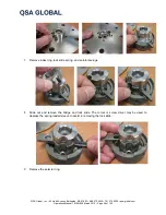
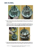
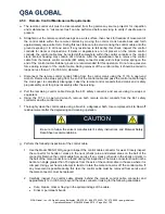
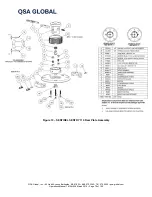
Place one of the cable adapters in the lower control crank housing. Place one end of the wear strip
against the cable adapter then fit the rest in the track of the housing. Fit the other cable adapter in
place to retain the wear strip.
CAUTION
Wear safety glasses
when inserting the wear strip. It will be under tension and could
suddenly fly out during assembly
.
Place the drive wheel in the lower half of the control crank housing making sure the spacer rings are
between it and the wheel bearings if applicable.
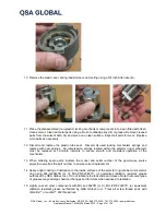
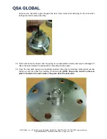
Assemble the two brake jaws, brake bearing and brake arm. The angled sides of the brake jaws
should be facing the retract side of the control crank housing.
Place the upper control crank housing over the assembly while keeping them level and press them
together.
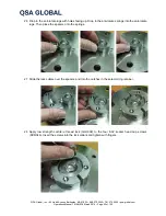
Check that the control crank mechanism is properly assembled by turning the shaft. It should spin
freely.
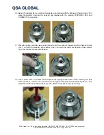
Check the operation of the friction brake while holding both halves of the control crank housing
together tightly. If it does not function correctly, check for faulty assembly or excessively worn brake
jaws.
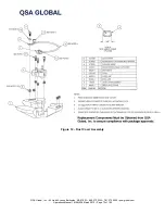
As applicable, mount the control crank housing on the frame or handle with the four bind head screws
and stop nuts. Secure the crank arm to the shaft using the 5/16 in washer and hex bolt.
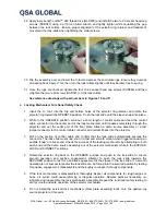
For reel type controls, secure the odometer cover to the mounting plate with two bind head screws.
Secure the odometer's reset knob to the shaft by tightening the two Allen head screws, leaving
clearance between the knob and the cover.
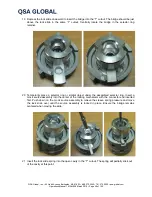
After assembly, perform a check to ensure the control crank will turn freely. Set the brake lever to the
ON position and attempt to turn the handle using moderate pressure. Do not apply excessive force.
Run a section of the control cable through the control crank to ensure the control crank operates
easily without snags or resistance.
If applicable, make sure the odometer turns when the crank handle is turned. If the odometer does
not function during this test, check for improper assembly or damaged parts.
k.
Clean the 661 safety connector assembly using a brush and solvent. Ensure the movable jaws of the
safety connector are not excessively loose or worn where they swivel in the clevis pins. Examine the
connector collar for bent or loose connecting pins and excessive wear on the inner-mating surface.
Examine the face of the connector body where the control cable protrudes and verify that long-term
usage has not chamfered the area.


