background image

30

TROUBLESHOOTING

If no sound in the theater...

If one audio channel is missing ...

- If PROC inputs are active, then monitor the AMPS outputs (next step).

- If PROC inputs are not active, check the cable between the DCM and the Cinema Processor or the
Cinema Processor itself.

• Verify the Cinema Processor is providing active inputs to the DCM by monitoring the PROC inputs (see
pages 11 and 12 if you are unsure of how to select audio to monitor).

• Verify the amplifiers outputs by monitoring the AMPS outputs.

- If no amplifier audio, check that the amplifiers are turned on and their gain controls are set to
some useful level (not fully counter-clockwise or minimum).

- Also check the DCM front panel LOAD FAULT LED; if it is illuminated, press the DIAGNOSTICS
button and an LED will light above any channel indicator that has an open or shorted speaker cable.
Use standard audio troubleshooting techniques to isolate which of the amplifier channels may have
the fault.

- If the LOAD FAULT LED is not illuminated, switch the BYPASS switch to the EMERGENCY position
and verify center channel audio is present. If it is, you know that the cables, amplifier, and speaker
for the center channel are okay. If you switch this back and still have no sound, check the DCM
configuration file for proper signal routing using the DCM Manager software.

• Verify the amplifier for the respective channel is on and its gain controls set to a useful setting.

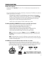
• Verify the DataPort cable for the respective amplifier is seated properly and secured to its respective
connectors.

• Verify none of the channels are muted in the DCM Manager configuration. Connect with the DCM Man-
ager software and upload the configuration to the host PC. See if the MUTE tab shows any channels muted;
correct any settings as required. Check the configuration file for proper signal routing.

If some of the front panel LEDs don’t illuminate....

• The DCM will only select and monitor amplifier channels that have been enabled using the DCM Man-
ager program. The front panel LEDs and audio monitoring only allow use of channels set in the software.
Connect the host PC to the DCM and run the DCM Manager program. Upload the current configuration and
check the settings in the General tab/ Installed Outputs section. Make any required changes and download
to the DCM. Save your file and verify proper front panel LED operation.

Summary of Contents for DCM-1

Page 1: ...1 DCM Series TD 000106 00 TD 000106 00 Rev B Digital Cinema Monitor Crossover System USER MANUAL DCM 1 DCM 2 DCM 3...

Page 2: ...arts stands tripods brackets interconnecting cables or software specified by QSC Audio Products When moving or transporting using a cart use caution to avoid injury from tip over 13 Unplug the apparat...

Page 3: ...reement DCM Manager is a trademark of QSC Audio Products Inc Windows and Windows 98 NT XP and 2000 are trademarks of Microsoft Corporation IBM is a registered trademark of IBM Corporation Pentium is a...

Page 4: ...via a personal computer PC These modifications can be password protected for tamper proof system control Fast Setup with Easy Wiring Your DCM takes advantage of the unique DataPort found on DCA Series...

Page 5: ...G 6 feet long 120V 5 warranty card 6 QSC store catalog 7 QSC accessories sheet 8 DCM Manager Application Disk SYSTEM REQUIREMENTS and UNPACKING DCM Manager software is designed to control one DCM hard...

Page 6: ...ers The DataPort connections replace amplifier audio input cables and amplifier output monitor connections Another unique feature of the QSC Cinema System is the ability to automatically analyze volta...

Page 7: ...for routing to the QSC amplifiers SYSTEM CONCEPTS 3 DSP processing Digital filtering of audio signals is known to have several advantages over analog solutions DSP digital signal processor IC chips al...

Page 8: ...ostics fault indicator LEDs 8 Monitor output test points 9 Bypass switch DCM 1 FRONT PANEL 1 Emergency bypass level controls 2 Subwoofer output 3 Hearing Impaired system output 4 Audio input connector...

Page 9: ...t indicator LEDs 8 Monitor output test points 9 Bypass switch DCM 2 FRONT PANEL 1 Emergency bypass level controls bypass switches 2 DataPort outputs to amplifiers 3 Audio input connector from Cinema P...

Page 10: ...ault indicator LEDs 8 Monitor output test points 9 Bypass switch DCM 3 FRONT PANEL 1 Emergency bypass level controls bypass switches 2 DataPort outputs to amplifiers 3 Audio input connector from Cinem...

Page 11: ...f the AMPS PROC switch The LEDs directly over the PROC AMPS switch indicate what selected function the Monitor Select buttons will have When the PROC LED is illuminated the Monitor Select buttons will...

Page 12: ...SR1 signals to the speakers closest to the screen SL2 and SR2 in the next set of speakers further away from the screen and the SL3 and SR3 connections furthest back in the theater In Surround Decoder...

Page 13: ...there is no amplifier detected at that DCM amplifier connector If the AMP LED is on the amplifier on at that output is measuring a short or an open on its output terminals REMEMBER If you configured...

Page 14: ...osition the PROC center channel signal is routed to a passive crossover no power is required and then to the center channel amplifier There are level adjustments on the rear panel for balanc ing the h...

Page 15: ...utputs with separate processing are included for additional theater configuration flexibility The rear panel labeling on the DCM has all of the information required by an audio installer When starting...

Page 16: ...MODE switch DCM 2 and DCM 3 only internally routes the Center channel input signal through the 2 way passive crossover or the 3 way passive crossover The BI AMP ROUTING switch DCM 2 and DCM 3 only rou...

Page 17: ...or the terminal strip connection but not both at the same time This connection cannot be monitored or include any of the Fault Analysis functions because there are no connec tions back from this exter...

Page 18: ...rer for optimum sound performance Select speakers for each of the physical locations L C R SL SR SUB and a large portion of the system calibration is finished NOTE QSC updates these files regularly as...

Page 19: ...ners on the bottom and press firmly to activate the pressure sensitive adhesive If rack mounting the DCM secure the DCM to the rack rails using four machine screws and washers of the proper size Most...

Page 20: ...031 00 Method 2 The DCM is first installed from the front of the rack and secured to the front rack rails Temporarily secure the rear ears to the rear rack rails and select the appropriate mounting po...

Page 21: ...d makes any required connection changes fast easy and reliable REQUIRED CABLES typical system AC MAINS CONNECTION Locate the IEC style AC power cord supplied with your DCM Identify the IEC end molded...

Page 22: ...d to an available RS 232 port on the host PC The PC must have QSC s DCM Manager software installed on its hard drive Start the DCM Manger pro gram and verify RS 232 communication between the PC and DC...

Page 23: ...tion Connect the other end of the cable to the DataPort on the correspond ing channel s DCA amplifier DATAPORT CONNECTION Use QSC DataPort cables Contact QSC s Techni cal Services Group if you would l...

Page 24: ...h the processor manufacturer We recommended that you purchase a standard 25 pin cable from any of the well known cinema industry cable suppliers CINEMA PROCESSOR CONNECTION INSTALLATION Connections Ci...

Page 25: ...oring available for the sub channel signal if this connection is used POWERED SUBWOOFER CONNECTION DCM 1 Terminals DCM 2 and 3 Terminals DCM 1 Terminals DCM 2 and 3 Terminals Output Level Impedance 11...

Page 26: ...the amplifiers INSTALLATION Connections Surround Insert SURROUND INSERT CONNECTION TO SURROUND EX DECODER Pinout Configuration typical 9 pin SubD female on DCM end to loose wires attaching to surround...

Page 27: ...need to make level adjustments INSTALLATION System Calibration SYSTEM CALIBRATION When installing a typical cinema sound system most of the calibration involves the Cinema Processor Refer to the user...

Page 28: ...ic EQ screen EQ and Horn EQ driver and channel delay polarity and gain adjustments which can be used as additional compensation for speaker and installation characteristics Driver delay settings compe...

Page 29: ...t to a useful level not fully counterclockwise Verify the desired active monitor source is selected by pressing the AMPS PROC selector button and observing the illuminated LEDs beneath channels select...

Page 30: ...io is present If it is you know that the cables amplifier and speaker for the center channel are okay If you switch this back and still have no sound check the DCM configuration file for proper signal...

Page 31: ...ections from the DCM to the center channel amplifier Verify the Cinema Processor and center channel amplifier are ON and functioning Verify the center channel amplifier s Gain controls are set to a us...

Page 32: ...rsion 24 bit delta sigma 128x oversampled Filter Topology 24 bit digital IIR Subwoofer Output Adjustment 3 to 18 dB in 0 1 dB steps Dynamic Range 99 dB THD N at 12 dBu Input Level 0 02 20 hertz to 20...

Page 33: ...VAC 260 VAC 50 60 Hz Fuse Littlefuse 218 001 or Bussman S5504 1A 250 Volt 1 Amp Safety Agency Approvals UL 6500 CSA EMC Approvals FCC Class A Connectors AC Power IEC style detachable cord receptacle R...

Page 34: ...does not extend to any product which has been subjected to misuse neglect accident improper installation or where the date code has been removed or defaced QSC shall not be liable for incidental and o...

Page 35: ...35 This page intentionally left blank...

Page 36: ...36 QSC Audio Products Inc 1675 MacArthur Boulevard Costa Mesa California 92626 USA QSC and the QSC logo are registered with the U S Patent and Trademark Office 2002 QSC Audio Products Inc...

Reviews: