8
TD-000517-01-A
Connections
AC Power Cord
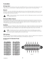
Connect the AC power cord into the AC power inlet on the back of the DCM. Plug the AC line connector into an AC outlet. The power supply on the
DCM accepts from 100 – 240V, 50 to 60 Hz. If a different type of IEC power cord is required, consult QSC’s Technical Services Group.
Network
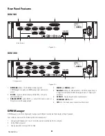
Figure 2 item 1 is used to connect the DCM to a network switch to allow setup, control and monitoring over Ethernet. Connect one end of a data
communications cable terminated with an RJ45 plug into the Ethernet receptacle on the rear panel of the DCM. Ensure that the lock tab on the
cable engages with the RJ45 receptacle on the DCM.
NOTE!:
The data communications cabling must be rated CAT-3 or better for 10 Mbps network connections or rated CAT-5 or better
for 100 Mbps network connections.
Hearing and Monitor Outputs
The Hearing Impaired and Monitor outputs are balanced outputs that are combined into a single 5-terminal Euro style receptacle. This combo
receptacle includes a common ground for both the HI and Monitor outputs. Terminate the mating 5-terminal Euro plug and insert it into the DCM
rear panel receptacle as shown in the image to the right. The DCM rear panel label provides a pin-out of the receptacle signals. A standard
3-terminal Euro style plug may be used if only one output is required.
DataPorts
QSC DataPort connectors on the DCM rear panel interface with QSC amplifiers having v1 DataPorts. These DataPorts are included on DCA and PL3
series amplifiers. All DataPorts use a HD15 connector and connect to QSC amplifiers using HD15 male to HD15 male data communications cables.
Connect the DataPort cables between the DCM DataPorts and the amplifier DataPorts. Finger-tighten the thumb screws on the connectors.
NOTE!:
The DataPort cables use the same connector format as VGA cables. Some off-the-shelf VGA cables may work with
satisfactory results, however, not all will. To make sure the system operates correctly, only QSC supplied DataPort cables should be
used. A variety of lengths are available through QSC’s Technical Services Group.
USB Interfaces
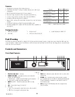
Figure 1 item 9 illustrates the front-panel USB Type B port provided for directly connecting to a computer. All configuration and local management of
the DCM via DPM Manager software can be performed through this portal. The USB Type B is a standard cable.
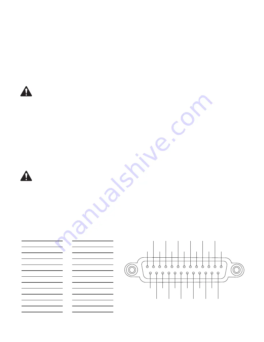
Analog Inputs (1-8) Connector Pinout
25-pin female
— Figure 4 —
15
16
17
18
19
20
21
22
23
24
25
2
1
3
4
5
6
7
8
9
10
11
12
13
14
Pin #
Description
1
Chassis ground
2
Left +
3
Left extra -
4
Chassis ground
5
6
Right extra -
7
Chassis ground
8
Right +
9
Chassis ground
10
Surround left -
11
Surround right -
12
Subwoofer -
13
Chassis ground
Pin #
Description
14
Left -
15
Chassis ground
16
Left extra +
17
Center -
18
Chassis ground
19
Right extra +
20
Right -
21
Chassis ground
22
Chassis ground
23
Surround left +
24
Surround right +
25
Sub
Shell
Chassis ground


