VI. DCM HARDWARE DESCRIPTION
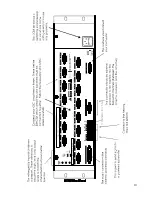
A. Front Panel Features
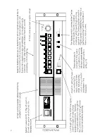
The front panel of the DCM series resembles traditional cinema monitor products. This was done to
allow a typical machine room projectionist a well known and easy to understand user interface. This
also follows our design goal of presenting an easy to understand product to the user while still offering
a state-of-the-art cinema sound control system for installation technicians and advanced users.
1. Power On/Off
The power on/off switch acts as a master control for not only the DCM, but
also all of the amplifi-
ers
connected into the system (as long as the amplifier power switches are "on").
This is possible
because the DataPort connections on all of the amplifiers have a standby control pin which is
grounded when the DCM is turned off. Because of the unique zero inrush feature on DCA amplifi-
ers, no additional startup sequencing is required.
The Emergency Bypass circuitry requires that the center channel amplifier remain on if the front
panel switch is in the EMERGENCY position. This causes the following situations:
When the Emergency Bypass = NORMAL, DCM power on/off also switches the QSC amplifiers
between on/standby.
When the Emergency Bypass = EMERGENCY, DCM power on/off also switches the QSC amplifiers
between on/standby
except
the center channel amplifier (connected to DCM DataPort B) which
remains on.
2. Audio Monitoring
All of the processor and amplifier audio signals can be routed to a monitor speaker on the front
panel so one can verify proper operation.
The
PROC
/
AMP
button selects monitoring of the cinema processor or amplifier output signals.
PROC
is short for PROCESSOR and routes the signals that are coming from the cinema processor
(at the DCM input) to the front panel speaker. The
AMP
selection monitors the signals from the
output of the QSC amplifiers (right from the speaker output terminals!). After the
AMPS
/
PROC
choice has been made, the individual channel buttons determine exactly which signals are routed
to the front panel monitor speaker.
Processor monitoring is very simple. Select the
PROC
position and then select the desired
L,LC,C,RC,R,SL,SR, or SUB position.
Amplifier monitoring includes selections for the L,LC,C,RC,R channels (just like the
PROC
selec-
tions), but offers additional monitoring of all of the additional amplifier outputs.
There are physically 3 Surround Left (SL) and Surround Right (SR) amplifiers available for connec-
tion to the speakers on the theater side walls. These are able to create three distinct "zones"
where volume controls can be adjusted.
One typical installation would be to connect the SL1 and SR1 signals to the speakers closest to
the screen. SL2 and SR2 in the next set of speakers further away from the screen and the SL3 /
SR3 connections furthest back in the theater. In Surround Decoder applications, the SL3 / SR3
12
Summary of Contents for DCM series
Page 1: ...DCM Series Digital Cinema Monitor Crossover System U S E R M A N U A L...
Page 3: ......
Page 4: ......
Page 14: ...7...
Page 15: ...8...
Page 16: ...9...
Page 17: ...10...
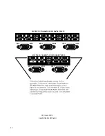
Page 18: ...DCM 2 and DCM 3 DataPort ABC and EF Detail 11...
Page 55: ......
Page 56: ...1675 MacArthur Boulevard Costa Mesa CA 92626 1468...

