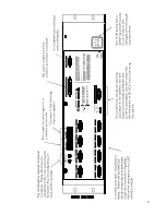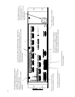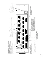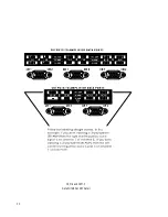
amp with 3 surrounds and 4 subs). Now you can follow the rear panel text which shows both
channel position (L or C or R, etc) and the frequency output (LO, MID, HI, etc).
Connect the L-LO output to the correct amplifier driving the left positional speaker (and the low
frequency transducer), and L-HI to the amplifier driving the same speakers high frequency trans-
ducer, etc.
NOTE:
There is no signal processing of the surround signal in a standard DCM-2 or DCM-3, how-
ever, the system is "Active Surround Ready". Please contact the QSC factory for more information.
==========
WARNING:
Incorrect frequency connections can damage tranducers. Physically verify proper
connections AND listen to each individual transducer at very low volume before applying full au-
dio power.
==========
2. From Processor Output
This connection is from the cinema processor, and is the main input of all film sound into the DCM
unit. The 25 pin connector is an industry standard type and pinout, and will connect into your sys-
tem very easily. These cables are available from several cinema supply houses. Refer to Appen-
dix 1 for the pinout detail.
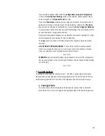
3. RS-232 Connection
This connects to the RS-232 serial port on an IBM compatible PC. All of the crossover functions
and many other features are able to be viewed and modified using Windows control software
which communicates to the DCM via this connection. Appendix 1 details the pinout of this cable.
4. Surround Insert
The insert connector offers an extremely simple method of routing the surround signals out of the
DCM to an external processor box, and then back into the DCM for further routing and monitoring.
Appendix 1 details this cable.
5. Emergency Bypass Levels and Routing
These are used to adjust the passive crossover used by the Emergency Bypass feature. The signal
level of the passive crossover outputs sent from the DCM to the center channel amplifier can be
adjusted to best suit the center channel transducer sensitivities. The
BYPASS CROSSOVER
MODE
switch (DCM-2 and DCM-3 only) internally routes the Center channel input signal through
the 2-way passive crossover or the 3 way passive crossover. This signal path is only active if the
front panel Bypass switch is in the Emergency position.
15
Summary of Contents for DCM series
Page 1: ...DCM Series Digital Cinema Monitor Crossover System U S E R M A N U A L...
Page 3: ......
Page 4: ......
Page 14: ...7...
Page 15: ...8...
Page 16: ...9...
Page 17: ...10...
Page 18: ...DCM 2 and DCM 3 DataPort ABC and EF Detail 11...
Page 55: ......
Page 56: ...1675 MacArthur Boulevard Costa Mesa CA 92626 1468...

