7
8
Assembling the Array
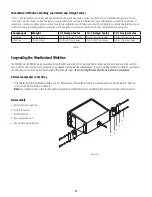
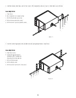
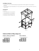
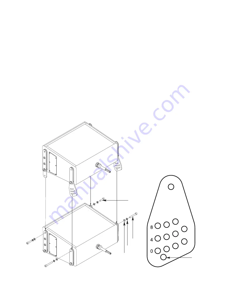
1. Place the pre-assembled top or middle loudspeaker assembly on top of the bottom (or another middle) loudspeaker, aligning the rigging links with
their respective rigging links on the bottom loudspeaker as shown below.
2. Secure the top loudspeaker to the bottom loudspeaker with two L70 cap screws in the rear, and two L70 (L50) cap screws in the front. Torque all
cap screws to 60 in.-lbs.
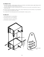
Note: Each hole on the Rear-center Rigging Link represents 1 degree of angle for setting the splay. The rows are numbered 0, 4, and 8, indicating holes
0 - 10. Use QSC's EASE Focus to determine the proper angles.
You can download EASE Focus at (http://www.qscaudio.com/products/software/EASE_Focus/ease_focus.htm).
Assembly order
a. M10 Lock Washer (front new, rear removed earlier)
b. M10 Flat Washer (front new, rear removed earlier)
c. M10 Hex Socket Cap Screw (rear - removed earlier)
d. M10 Hex Socket Cap Screw 70L (50L) (new)
a
d
c
b
– Figure 12 –
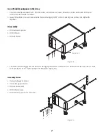
Used for shipping
only.
– Figure 13 –
Summary of Contents for GP218-wx
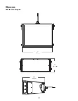
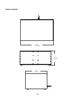
Page 12: ...11 Dimensions WL3082 wx Loudspeaker 20 508 mm 9 5 241 3 mm 15 5 397 mm ...
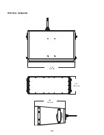
Page 13: ...12 WL2102 wx Loudspeaker 27 25 692 mm 11 75 298 5 mm 18 5 469 9 mm ...
Page 14: ...13 GP218 wx Subwoofer 47 32 1201 8 mm 22 0 560 mm 30 765 mm ...
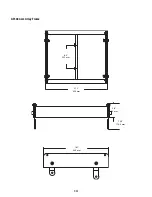
Page 15: ...14 AF3082 wx Array Frame 8 0 203 mm 21 1 536 mm 7 06 179 4 mm 3 8 95 mm 18 1 459 mm ...


