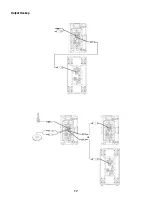
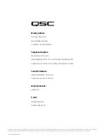
background image

14

Subwoofer Polarity

Polarity (sometimes improperly referred to as phase) refers to the voltage of an input signal and whether it is a 
positive or negative voltage at any given time. In most cases a positive voltage causes a woofer cone to move 
forward with respect to the cabinet orientation, and a negative voltage then moves the woofer cone backward. 
Most importantly, speakers reproducing the same signal or signals that are adjacent in frequency must have the 
same polarity to get the maximum output. This is most important for low frequencies. Polarity can be altered by 
incorrect wiring or mixer control settings. 

(Figure 10)

When using the KSub with K Series full range loudspeakers, NORMAL polarity will result in the best bass response 
IF the full range loudspeakers are sitting on or very close to the subwoofers. If the subwoofers are some distance 
away from the full range loudspeakers, polarity change may be of benefit. Start with all subwoofer POLARITY 
switches in the NORMAL position. Then, with the system at or near expected operating levels, change the polarity 

of each subwoofer INDIVIDUALLY. Walk around the venue and assess the overall bass response. Select the polarity 

that results in the best overall system bass response.

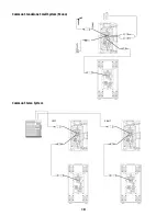
When using only one KSub and connecting a LEFT and RIGHT stereo signal, start with the polarity switch in the 
NORMAL position. With the system at a reasonable level, change the POLARITY switch and evaluate which polar-
ity results in the most low-frequency output.

Additional Features

Standby

All K Series models are equipped with an automatic standby feature to conserve energy when the systems are not 
in use. If no signal is present on any input of a K Series system or the gain knob is turned to off for five minutes, 
the power amplifier will go into standby and the green STANDBY LED will illuminate. No other LEDs will illuminate 
when the unit is in standby; this includes both the Rear Power LED and the Front Power LED. In this mode, the 
amplifier will be powered down. A small amount of voltage will continue to flow from the AC power source into 
the power supply of the K Series power module. This voltage will keep the power supply and DSP “awake” to 
reduce turn on time when the system is brought out of standby. The power up time of the amplifier is negligibly 
small and is shorter than the latency of the DSP, so no signal will be cut off when the K Series system is brought 
out of standby. A K Series loudspeaker can also be brought out of standby manually by turning the power switch 
off and then back on.

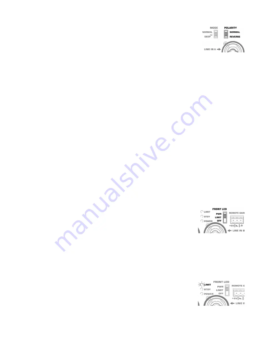
Front Power LED Functions

The Front Power LED may be set to any of three modes by the rear-mounted Power LED switch. 

(Figure 11)

• 

From the factory, the Power LED switch is set to the PWR position. The Front Power LED will illuminate when 
the power switch is in the ON position and the unit is not in Standby. 

• 

In the “OFF” position, the Front Power LED will not illuminate. This setting is recommended in applications 
where the Front Power LED may be visually objectionable while the unit is operating. 

• 

In the LIMIT setting the Front Power LED will track the LIMIT LED on the rear of the unit. When the K Series 
is in Limiting (meaning that one or more of the limiters is engaging to protect some part of the system) the 
Front Power LED will glow brighter in response to the limiting function. This allows the system operator to have 
awareness of the status of the limiters without needing to see the rear of the unit. For more information see the 
section below on the Rear LIMIT LED. When not in limiting and when the unit is not in standby, the front power 
LED will be illuminated dimly.

Rear LIMIT LED

The red LIMIT LED can indicate that limiting has taken place to protect and avoid damage to the amplifier or loud-
speaker. 

(Figure 12)

 If the signal level at any frequency is too high, the DSP will limit the signal to prevent damage 

and the red LIMIT LED will illuminate. If the amplifier is too hot because the SPL is too high or the environment is 
too hot, the red LIMIT LED will be illuminated. If the red LIMIT LED is on when both Gain controls are at mini-
mum, your K Series loudspeaker requires service by qualified personnel. 

– Figure 10 –

– Figure 11 –

– Figure 12 –

Summary of Contents for K series

Page 1: ... 200 mm 2 way loudspeaker system K10 90 1000 W active 10 250 mm 2 way loudspeaker system K12 75 1000 W active 12 300 mm 2 way loudspeaker system KSub Dual 12 300 mm 1000 W active 4th order bandpass subwoofer system TD 000280 00 B TD 000280 00 B ...

Page 2: ...for the replacement of the obsolete outlet Do not cut off the grounding plug or use an adapter that breaks the grounding circuit This apparatus must be properly grounded for your safety 10 Protect the power cord from being walked on or pinched particularly plugs convenience receptacles and the point where they exit from the apparatus 11 The appliance coupler is the AC mains disconnect and should r...

Page 3: ...se visit www qscaudio com Contact us at 800 854 4079 or visit our website at www qscaudio com FCC Statement NOTE This equipment has been tested and found to comply with the limits for a Class B digital device pursuant to Part 15 of the FCC Rules These limits are designed to provide reasonable protection against harmful interference in a residential installation This equipment generates uses and ca...

Page 4: ... points 8 Tilt Direct dual angle pole socket 9 Slip resistant feet K10 1 ABS enclosure 2 Steel grille 3 Front power LED 4 Cast aluminum handles 5 Power module 6 M10 installation points 7 M5 yoke attachment points 8 Tilt Direct dual angle pole socket 9 Slip resistant feet 1 6 4 7 7 5 6 3 2 7 9 8 9 7 1 4 4 4 5 6 6 3 2 8 9 9 7 7 7 7 Features ...

Page 5: ...7 M5 yoke attachment points 8 Tilt Direct dual angle pole socket 9 Slip resistant feet KSub 1 Birch plywood enclosure 2 Front power LED 3 Acoustic port 4 Cast aluminum handles 5 Power module 6 M20 threaded pole receptacle 7 3 heavy duty casters 8 Slip resistant feet 1 4 4 4 5 6 6 3 2 8 9 9 9 7 7 7 7 7 1 4 4 5 6 3 2 8 7 7 ...

Page 6: ...0 and K12 also have features designed for various suspen sion methods They feature M10 threaded inserts for suspension with eyebolts There are also yoke accessories model numbers K8 YOKE K10 YOKE K12 YOKE for each model that can mount either to the sides of the cabinet or to the top and bottom These yokes allow for rigid mounting to structures and rotation of the speaker system Figure 3 For extra ...

Page 7: ...le mounted on a 35 mm diameter loudspeaker support pole When pole mounted to the KSub pole length must not exceed 28 5 inch 724 mm K12 The K12 was designed to sit on the floor stage subwoofer enclosure be suspended or be pole mounted on a 35 mm diameter loudspeaker support pole When pole mounted to the KSub pole length must not exceed 26 5 inch 673 mm KSub The KSub was designed to sit on the floor...

Page 8: ...10 KIT or an M10 forged shoulder eyebolt with a thread length no more than 0 8 inch 20 mm Contact QSC Technical Services department for complete information Cooling in Installed Applications This is a self powered loudspeaker containing an internal power amplifier that produces heat Allow a minimum of 6 152 mm clearance at cabinet back for convection cooling Keep anything that might restrict airfl...

Page 9: ...will extinguish and the blue POWER indicator LED will illuminate Rear LED POWER Indicator The blue LED POWER indicator on the rear panel will illuminate when the AC Power switch is in the ON position the unit is not in standby the AC mains power cord is connected properly and the AC mains are functioning properly The rear LED POWER indicator will extinguish when the AC Power switch is in the off p...

Page 10: ...ot illuminate the input is not receiving any signal or the level of the signal is significantly low Check all connections and the status of the device delivering the signal Channel B will accept Line Level input only by connecting a male XLR cable or a male 1 4 phone cable either TS or TRS type may be used Channel B will also accept mono or stereo Line Level input on a pair of RCA phono jacks Gain...

Page 11: ...is affects the amount of signal sent to the amplifier and then to the loudspeaker components The green SIGNAL LED will illuminate when signal is present regardless of the amount of gain as set by the Gain knob If the LED does not illuminate the input is not receiving any signal or the level of the signal is significantly low Check all connections and the status of the device delivering the signal ...

Page 12: ...still Line Level WARNING Do not connect the POST GAIN LINE OUTPUT of a K Series system to any INPUT of the SAME UNIT This output is designed to send signal to OTHER K Series units or to other audio equipment Failure to follow this warning may result in very unpleasant sounds produced at extremely high output volumes Output Connections KSub Both Channel A and Channel B have discrete direct outputs ...

Page 13: ...ng in a very musical acoustically transparent system DSP User Functions Low frequency EQ On the K8 K10 and K12 there are three low frequency settings From the factory the switch is set to NORM This means that the loudspeaker system is producing a normal low frequency signal through the woofer This is the standard setting for most applications Figure 7 When using one of the top boxes with a subwoof...

Page 14: ...wered down A small amount of voltage will continue to flow from the AC power source into the power supply of the K Series power module This voltage will keep the power supply and DSP awake to reduce turn on time when the system is brought out of standby The power up time of the amplifier is negligibly small and is shorter than the latency of the DSP so no signal will be cut off when the K Series s...

Page 15: ...m a single poten tiometer by connecting the pins of multiple K Series speakers together A relay or manual connection can be made between the pin and the pin to put the K Series system into standby mode after 5 minutes WARNING Do not put more than 5V or less than ground on the pin or else damage may occur Do not connect the pin directly to the pin Schematics of Proper Wiring for Gain Attenuator Whe...

Page 16: ...16 Applications Input Hookup Output Hookup ...

Page 17: ...17 Output Hookup OR ...

Page 18: ...18 Common Standalone Small System Mono Common Stereo System LEFT RIGHT ...

Page 19: ...ns 11 280 mm K8 Top Front Side 17 7 450 mm 10 6 269 mm 12 6 320 mm K10 Top Front Side 20 4 519 mm 11 8 300 mm 14 356 mm K12 Top Front Side 23 7 603 mm 14 356 mm Front Side 14 356 mm KSub Top 26 665 mm 28 1 714 mm ...

Page 20: ...andby Limit Connectors Balanced female XLR line mic level input Balanced female XLR line level input Dual Balanced male XLR full range line level out Balanced male XLR mix out Stereo RCA line level input Remote gain control Locking IEC power connector Dual balanced female XLR line level input Dual Balanced male XLR full range line level out Remote gain control Locking IEC power connector Cooling O...

Page 21: ...ty of their respective owners Patents may apply or be pending Mailing Address QSC Audio Products LLC 1675 MacArthur Boulevard Costa Mesa CA 92626 1468 USA Telephone Numbers Main Number 714 754 6175 Sales Marketing 714 957 7100 or toll free USA only 800 854 4079 Customer Service 714 957 7150 or toll free USA only 800 772 2834 Facsimile Numbers Sales Marketing FAX 714 754 6174 Customer Service FAX 7...

Reviews: