


15
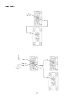
Remote Gain Attenuator
A 3 pin “Euro” connector has been provided to adjust the volume of the K Series loudspeaker or put the system
into standby.
(Figure 13)
By varying the voltage on the
pin b5V (provided on
pin) and
ground (
pin), the volume can be linearly controlled. The voltage on the
pin can be created by using a
potentiometer or provided from an external source. Many K Series systems can be controlled from a single poten-
tiometer by connecting the
pins of multiple K Series speakers together.
A relay or manual connection can be made between the
pin and the
pin to put the K Series system into
standby mode after 5 minutes.
WARNING: Do not put more than +5V or less than ground on the
pin or else damage may
occur. Do not connect the
pin directly to the pin.
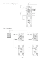
Schematics of Proper Wiring for Gain Attenuator
When using a single potentiometer for one loudspeaker.
(Figure 14)
When using a single potentiometer for multiple loudspeaker.
(Figure 15)
Wiring to the 3 pin “Euro” connector.
(Figure 16)
– Figure 13 –
– Figure 16 –
– Figure 14 –
– Figure 15 –


