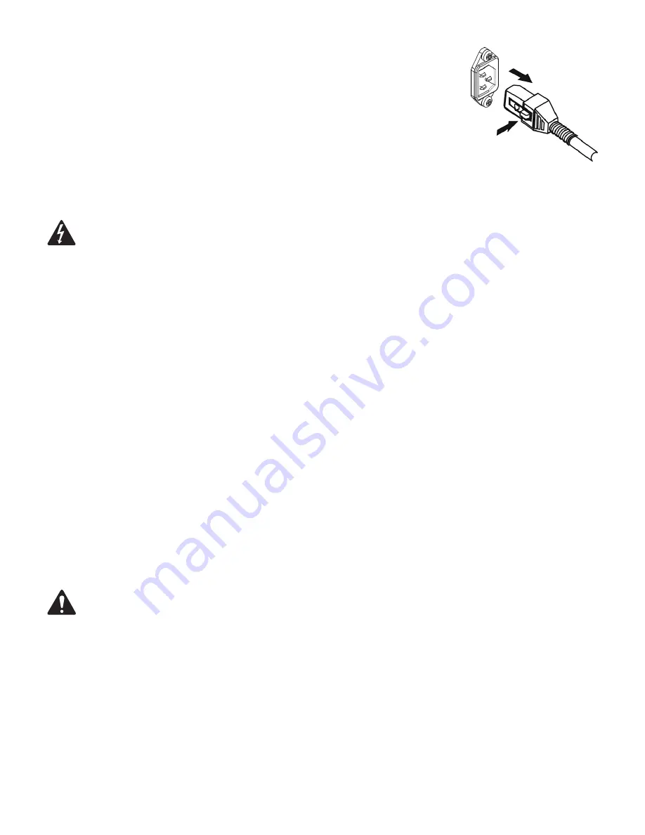
background image

9

AC Mains

Connect AC power to the IEC socket on the back of the amplifier by locating the IEC connector-end of the 
AC power cord and inserting it fully into the IEC inlet on the power amplifier module. 

NOTE:

 Turn off the AC 

power switch before connecting AC power.

The V-LOCK power cord has a special latching feature to prevent the power cord from being unintentionally 

removed. The IEC plug and socket are both blue in color so the power cord can be identified as a K Series 
loudspeaker cord. If the QSC supplied cord becomes lost or damaged, a standard replacement 18 gauge IEC 

power cord may be used. However, the latching system will only function with a V-LOCK power cord available 

from QSC Audio Products, LLC.

The K Series is fed by a universal power supply. This power supply is capable of operating the system with input AC power voltages ranging  

from 100 - 240 VAC at 50 – 60 Hz.

Use only the power cable that is correct for your location. 

You may discard any other power cables, find an appropriate recycling opportunity or keep them if travel to other regions with the K Series product is likely.

AC Mains Disconnection

Turn the AC power switch to the off position. To remove the AC mains cord, grasp the IEC connector’s plastic body, press the yellow latch release but-
ton and pull, removing the connector from the socket.

Power Switch

Push in on the top of the rocker switch to apply AC mains power to the powered loudspeaker. Push in on the bottom of the rocker switch to turn the 
powered loudspeaker off.

When turned on, the green STANDBY indicator LED and the red LIMIT (limiter) indicator LED on the rear panel will illuminate; after a few seconds the 
red LIMIT indicator and the green STANDBY will extinguish, and the blue POWER indicator LED will illuminate.

Rear LED POWER Indicator

The blue LED POWER indicator on the rear panel will illuminate when the AC Power switch is in the “ON” position, the unit is not in standby, the 
AC mains power cord is connected properly, and the AC mains are functioning properly. The rear LED POWER indicator will extinguish when the AC 
Power switch is in the “off” position, AC mains power has been removed from the loudspeaker, or the amplifier enters standby.

If the rear LED POWER indicator does not illuminate when the Power switch is placed in the “on” position during the first 5 minutes of power being 

applied, verify the AC mains line cord is properly attached to the loudspeaker and plugged into the AC outlet. Verify the outlet is functioning properly.

If the AC mains cordset is serviceable and the AC mains outlet is operating properly, but the loudspeaker fails to operate, the loudspeaker may 
require servicing. Contact QSC’s Technical Services department.

System Power Sequencing

Proper power turn on/turn off sequencing can help to prevent unexpected sounds from being produced by the system (pops, clicks, 
thumps). These unintended sounds can be unpleasant and take away from the overall professionalism of the presentation. Always 

follow the rule that speakers are “last on, first off”.

Power On Sequence:

 Bring the output level control of the mixer (or other audio source) feeding your speakers to its minimum position. Turn on all 

source devices (CD players, mixers, instruments), turn on subwoofer, then turn on the “top-boxes” (K8, K10, K12). The level controls on your mixer 
may now be brought up.

Power Off Sequence:

 Turn off “top boxes,” turn off subwoofer, then turn off all source devices.

If a K Series speaker is being driven from the output of another K Series unit, it should be turned on after the unit feeding it signal, and turned off 
before the unit feeding signal.

Summary of Contents for K series

Page 1: ... 200 mm 2 way loudspeaker system K10 90 1000 W active 10 250 mm 2 way loudspeaker system K12 75 1000 W active 12 300 mm 2 way loudspeaker system KSub Dual 12 300 mm 1000 W active 4th order bandpass subwoofer system TD 000280 00 B TD 000280 00 B ...

Page 2: ...for the replacement of the obsolete outlet Do not cut off the grounding plug or use an adapter that breaks the grounding circuit This apparatus must be properly grounded for your safety 10 Protect the power cord from being walked on or pinched particularly plugs convenience receptacles and the point where they exit from the apparatus 11 The appliance coupler is the AC mains disconnect and should r...

Page 3: ...se visit www qscaudio com Contact us at 800 854 4079 or visit our website at www qscaudio com FCC Statement NOTE This equipment has been tested and found to comply with the limits for a Class B digital device pursuant to Part 15 of the FCC Rules These limits are designed to provide reasonable protection against harmful interference in a residential installation This equipment generates uses and ca...

Page 4: ... points 8 Tilt Direct dual angle pole socket 9 Slip resistant feet K10 1 ABS enclosure 2 Steel grille 3 Front power LED 4 Cast aluminum handles 5 Power module 6 M10 installation points 7 M5 yoke attachment points 8 Tilt Direct dual angle pole socket 9 Slip resistant feet 1 6 4 7 7 5 6 3 2 7 9 8 9 7 1 4 4 4 5 6 6 3 2 8 9 9 7 7 7 7 Features ...

Page 5: ...7 M5 yoke attachment points 8 Tilt Direct dual angle pole socket 9 Slip resistant feet KSub 1 Birch plywood enclosure 2 Front power LED 3 Acoustic port 4 Cast aluminum handles 5 Power module 6 M20 threaded pole receptacle 7 3 heavy duty casters 8 Slip resistant feet 1 4 4 4 5 6 6 3 2 8 9 9 9 7 7 7 7 7 1 4 4 5 6 3 2 8 7 7 ...

Page 6: ...0 and K12 also have features designed for various suspen sion methods They feature M10 threaded inserts for suspension with eyebolts There are also yoke accessories model numbers K8 YOKE K10 YOKE K12 YOKE for each model that can mount either to the sides of the cabinet or to the top and bottom These yokes allow for rigid mounting to structures and rotation of the speaker system Figure 3 For extra ...

Page 7: ...le mounted on a 35 mm diameter loudspeaker support pole When pole mounted to the KSub pole length must not exceed 28 5 inch 724 mm K12 The K12 was designed to sit on the floor stage subwoofer enclosure be suspended or be pole mounted on a 35 mm diameter loudspeaker support pole When pole mounted to the KSub pole length must not exceed 26 5 inch 673 mm KSub The KSub was designed to sit on the floor...

Page 8: ...10 KIT or an M10 forged shoulder eyebolt with a thread length no more than 0 8 inch 20 mm Contact QSC Technical Services department for complete information Cooling in Installed Applications This is a self powered loudspeaker containing an internal power amplifier that produces heat Allow a minimum of 6 152 mm clearance at cabinet back for convection cooling Keep anything that might restrict airfl...

Page 9: ...will extinguish and the blue POWER indicator LED will illuminate Rear LED POWER Indicator The blue LED POWER indicator on the rear panel will illuminate when the AC Power switch is in the ON position the unit is not in standby the AC mains power cord is connected properly and the AC mains are functioning properly The rear LED POWER indicator will extinguish when the AC Power switch is in the off p...

Page 10: ...ot illuminate the input is not receiving any signal or the level of the signal is significantly low Check all connections and the status of the device delivering the signal Channel B will accept Line Level input only by connecting a male XLR cable or a male 1 4 phone cable either TS or TRS type may be used Channel B will also accept mono or stereo Line Level input on a pair of RCA phono jacks Gain...

Page 11: ...is affects the amount of signal sent to the amplifier and then to the loudspeaker components The green SIGNAL LED will illuminate when signal is present regardless of the amount of gain as set by the Gain knob If the LED does not illuminate the input is not receiving any signal or the level of the signal is significantly low Check all connections and the status of the device delivering the signal ...

Page 12: ...still Line Level WARNING Do not connect the POST GAIN LINE OUTPUT of a K Series system to any INPUT of the SAME UNIT This output is designed to send signal to OTHER K Series units or to other audio equipment Failure to follow this warning may result in very unpleasant sounds produced at extremely high output volumes Output Connections KSub Both Channel A and Channel B have discrete direct outputs ...

Page 13: ...ng in a very musical acoustically transparent system DSP User Functions Low frequency EQ On the K8 K10 and K12 there are three low frequency settings From the factory the switch is set to NORM This means that the loudspeaker system is producing a normal low frequency signal through the woofer This is the standard setting for most applications Figure 7 When using one of the top boxes with a subwoof...

Page 14: ...wered down A small amount of voltage will continue to flow from the AC power source into the power supply of the K Series power module This voltage will keep the power supply and DSP awake to reduce turn on time when the system is brought out of standby The power up time of the amplifier is negligibly small and is shorter than the latency of the DSP so no signal will be cut off when the K Series s...

Page 15: ...m a single poten tiometer by connecting the pins of multiple K Series speakers together A relay or manual connection can be made between the pin and the pin to put the K Series system into standby mode after 5 minutes WARNING Do not put more than 5V or less than ground on the pin or else damage may occur Do not connect the pin directly to the pin Schematics of Proper Wiring for Gain Attenuator Whe...

Page 16: ...16 Applications Input Hookup Output Hookup ...

Page 17: ...17 Output Hookup OR ...

Page 18: ...18 Common Standalone Small System Mono Common Stereo System LEFT RIGHT ...

Page 19: ...ns 11 280 mm K8 Top Front Side 17 7 450 mm 10 6 269 mm 12 6 320 mm K10 Top Front Side 20 4 519 mm 11 8 300 mm 14 356 mm K12 Top Front Side 23 7 603 mm 14 356 mm Front Side 14 356 mm KSub Top 26 665 mm 28 1 714 mm ...

Page 20: ...andby Limit Connectors Balanced female XLR line mic level input Balanced female XLR line level input Dual Balanced male XLR full range line level out Balanced male XLR mix out Stereo RCA line level input Remote gain control Locking IEC power connector Dual balanced female XLR line level input Dual Balanced male XLR full range line level out Remote gain control Locking IEC power connector Cooling O...

Page 21: ...ty of their respective owners Patents may apply or be pending Mailing Address QSC Audio Products LLC 1675 MacArthur Boulevard Costa Mesa CA 92626 1468 USA Telephone Numbers Main Number 714 754 6175 Sales Marketing 714 957 7100 or toll free USA only 800 854 4079 Customer Service 714 957 7150 or toll free USA only 800 772 2834 Facsimile Numbers Sales Marketing FAX 714 754 6174 Customer Service FAX 7...

Reviews: