17
TD-000487-00
K Series Service Manual
4. Set the baffle assembly face down on a work surface.
5. Gently place the main enclosure assembly on top of the baffle assembly, paying close attention to the orientation. If
possible, connect the molex connector to the BOP.
Note
: Connecting the wiring harness to the BOP at this stage can be difficult. Perform that step after the baffle has been
installed by removing the BOP, connecting the harness, and reinstalling the BOP.
6. Verify that the small gap between the sides of the main enclosure and the baffle are even. Both sides of the front grille
must fit inside these gaps.
7. Fasten the screws that secure the baffle to the enclosure, starting with the corner screws.
5.4 High frequency transducer
The K8 and K10’s HF transducer is secured to the baffle by four mounting points that come out of the waveguide. Covering
the screws are four rubber plugs that allow the high frequency sound waves to propagate out correctly. The K12’s HF trans-
ducer is secured on the baffle as well, but behind the waveguide.
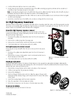
K8 and K10 high frequency transducer removal
It’s recommended to remove the baffle from the main enclosure but not re-
quired for HF transducer removal. Alternately, the BOP can be removed if you’re
okay with working in tight spaces.
1. Disconnect the yellow and yellow/black wires from the HF transducer’s
terminals.
2. Remove the 4 rubber plugs from the waveguide.
3. Remove the 4 screws that secure the HF transducer to the baffle.
4. The HF transducer can now be removed from the baffle.
K12 high frequency transducer removal
It’s required to remove the baffle from the main enclosure for HF transducer
removal.
1. Disconnect the yellow and yellow/black wires from the HF transducer’s
terminals.
2. Remove the 4 screws, 4 lock washers, and 4 normal washers that secure
the HF transducer to the baffle.
3. The HF transducer can now be removed from the baffle.
Diaphragm replacement
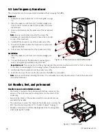
Instead of replacing the entire HF transducer, the transducer can be repaired by replacing the diaphragm. Replacing the
diaphragm can be much cheaper than replacing the entire HF transducer. Follow the instructions below to replace the dia-
phragm (QSC part number SR-000145-00).
1. Remove the 4 screws that secure the cover to the frame of the transducer.
2. Lift the cover away from the transducer assembly.
3. Remove the diaphragm.
4. Clean out the gap that the voice coil sits in. Wipe the edges of the gap with
isopropyl alcohol and spray the gap with compressed air to remove all contam-
inants inside.
5. Install the new diaphragm with the correct orientation.
6. Place the cover back on the transducer assembly.
7. Fasten the 4 screws to secure the cover on the transducer assembly.
Transducer installation
Simply follow the removal instructions in reverse.
Figure 5.4 - HF transducer removal on K8
and K10
Figure 5.5 - Diaphragm replacement.
Summary of Contents for K8
Page 2: ...2 QSC Audio Products LLC...


