21
TD-000487-00
K Series Service Manual
4. Partially lift the transducer out of the cabinet.
5. Disconnect the fastons from the transducer’s positive and negative terminals.
6. Lift and rotate the transducer out of the rear BOP cutout hole. It will barely fit.
Installation
1. Place the cabinet assembly on a padded surface front grille-side-down.
2. Rotate the LF transducer sideways and drop it down through the rear BOP cutout.
3. Connect the fastons to the transducer’s positive (green wire) and negative
(green/black wire) terminals.
Important note
: This connection must have high retention force! Crimp new
fastons (0.205” or 5.21 mm female, 14–16 AWG, insulated straight ) to the wiring
harness if the old ones are weak.
4. Gently lower the LF transducer into the cutout in the cabinet.
5. Fasten the 8 screws that secure the transducer to the baffle in a star pattern.
Note
: Be very careful when installing the screws. The screwdriver can easily slip
and pierce a hole in the surround or cone of the transducer.
6.3 Handles, threaded pole mount, and casters
Handle removal and installation notes
•
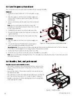
The handle is secured to the cabinet with machine screws (on the exterior of the cabinet) and mounting plates (on the
interior of the cabinet).
•
There is no easy way to remove or install new handles. Access to the interior of the subwoofer cabinet is required to
remove and install the handles. The BOP and at least 1 transducer must be removed to access them.
•
Reapply a small amount of thread locking fluid to the mounting plate when replacing the handles.
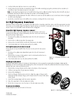
Figure 6.3 - The transducer will fit
through the cabinet’s BOP cutout
Figure 6.4 - The handle is secured by mounting plates on the interior of the
cabinet
Summary of Contents for K8
Page 2: ...2 QSC Audio Products LLC...


