background image

TD-000500 -01      -D


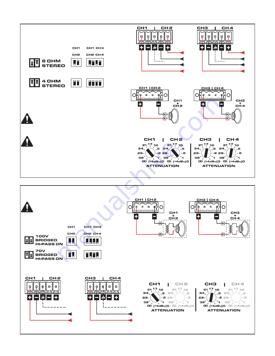
4 or 8-ohm Bridged Mode

Figure 22 – Figure 25    


CAUTION!: 


Do not connect any output 

to ground.

IMPORTANT: 


When using 4 or 8-ohm Bridged 

Mode, use both signal inputs of a channel pair (for 
example parallel CH1&2 inputs and parallel CH3&4 
inputs), and set the attenuation for each channel pair to 
the same level.

— Figure 22 —  

&

&

&


8+ 

 Bridged Load

4 - 8 

 Bridged Load

— Figure 23 —       


Inputs

— Figure 24 —   

Outputs

— Figure 25 —    

70V / 100V Bridge Mode


NOTE: 


80 Hz (high-pass fi lter) is auto-engaged 

in bridged 70 V and 100 V modes

Figure 26 – Figure 29

— Figure 26 —  

&

&

&

— Figure 27 —   


Bridged

Inputs

— Figure 28 —    


Bridged

Outputs

— Figure 29 —  

9

9


Minimum Load Impedance: 

•  70V Bridged = 16 

Ω

•  100V Bridged = 26 

Ω

Summary of Contents for SPA2-60

Page 1: ...product s enclosure that may be of sufficient magnitude to constitute a risk of electric shock to humans The intent of the exclamation point within an equilateral triangle is to alert the user to the...

Page 2: ...by Limiter Protect LEDs illuminating red To reduce the possibility of thermal limiting and allow proper heat dissipation we recommend that you keep the space directly above and to the rear of these a...

Page 3: ...4 1 3 2 4 1 Top Side Front Panel Top Side Front Panel B Two Amplifiers 19 inch Rack Front or Rear Facing Out Figure 3 1 2 2 2 3 2 4 6 5 1 6 6 Figure 3 4 3 3 4 5 1 1 6 2 4 3 3 4 5 1 6 1 2 Front Panel B...

Page 4: ...gure 4 1 1 2 2 3 6 Figure 4 1 2 3 3 2 1 2 3 Top Side Front Panel Top Side Rear Panel D Under Table or on Wall Figure 5 1 1 2 2 3 6 4 4 Not supplied use appropriate screws for mounting surface 5 Mounti...

Page 5: ...Spaces only when used with optional Plenum Kit FG 000995 00 sold separately Rack Mounting Options All Configurations Figure 8 Using the examples shown you can mount any of the amplifier configurations...

Page 6: ...tatus LEDs a Green Normal Signal Level b Amber Input or Output Overload Clipping or Thermal Limiting c Red Limit or Protect Mode d Red Thermal Limit or Protect Mode e Red Mute 1 5 Channel 1 Attenuator...

Page 7: ...OT TIN Output Connectors IMPORTANT Class 2 Wiring Figure 12 Figure 13 SPA 2 channel 1 SPA 4 channel 2 Figure 12 Figure 13 SPA 4 channel SPA 2 channel Input Connectors SPA 2 channel Connector Figure 14...

Page 8: ...nbalanced Inputs Figure 18 Figure 18 Unbalanced Inputs jumper between negative and ground Balanced Unbalanced Stereo Mode Figure 19 Figure 21 CAUTION Do not connect any output to ground Figure 19 Figu...

Page 9: ...and parallel CH3 4 inputs and set the attenuation for each channel pair to the same level Figure 22 8 Bridged Load 4 8 Bridged Load Figure 23 Inputs Figure 24 Outputs Figure 25 70V 100V Bridge Mode N...

Page 10: ...l controls for channel 1 2 are independent from channels 3 4 remote level control On the SPA 4 channel model closing the Standby Switch between the first two pins of either Ch1 Ch2 or Ch3 Ch4 causes a...

Page 11: ...anel Indicators Power Signal per channel Limit Mute Protect per channel Rear Panel Indicators Two colored LED Signal Limit Mute Protect per channel User configurable Operating Modes 4 channel or equiv...

Page 12: ...oll free USA only 800 772 2834 Facsimile Numbers Sales Marketing FAX 714 754 6174 Customer Service FAX 714 754 6173 World Wide Web www qsc com E mail info qsc com service qsc com 2015 2016 QSC LLC All...

Reviews: