background image

9

QLK INSTALLATION

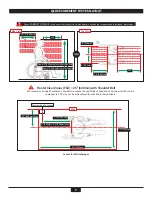
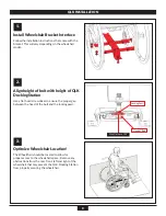
Install Wheelchair Bracket Interface

Follow the installation instructions that come with the 

bracket. This will vary depending on the wheelchair 

model.

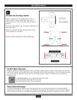
Align height of bolt with height of QLK 

Docking Station

Use a flat head screwdriver to ensure the proper gap 

between the head of the bolt and the locking pawl.

Optimize Wheelchair Location!

The Wheelchair should be located to allow for 

proper access to the wheelchair space.  Remove any 

obstructions from the rear, front, left and right of the 

wheelchair that may prevent the QLK Docking Station 

from properly securing the wheelchair. 

Max Distance .125”

Locking Pawl

Head of Bolt

3.

2.

1.

Summary of Contents for QLK

Page 1: ...INSTALLATION USER MANUAL...

Page 2: ...stered trademarks of Q STRAINT Inc Products mentioned herein are for identification purposes only and may be registered trademarks or trademarks of their respective companies All other brand names tra...

Page 3: ...ONTENTS IMPORTANT SAFEGUARDS AND WARNINGS 4 5 QLK SYSTEM OVERVIEW 6 QLK SECUREMENT SYSTEM LAYOUT 7 ELECTRICAL REQUIREMENTS 8 QLK INSTALLATION 9 10 QLK MOUNTING 11 14 SYSTEM OPERATION 15 QLK PRODUCT MA...

Page 4: ...HAIR SPACE The QLK Wheelchair Docking System wheelchair space defined as the surface where the wheelchair rests must include flooring frames or cross members capable of supporting the expected weight...

Page 5: ...jury or death and may tip over or be ejected from the wheelchair during normal vehicle travel emergency maneuvers or crashes The QLK Wheelchair Docking System has been successfully dynamically tested...

Page 6: ...MENTS SPEAKER AUDIBLE IGNITION 12 VDC SYSTEM POWER 12 VDC DASH CONTROLLER WIRELESS KEY FOB AUDIBLE AUXILIARY RELEASE SWITCH SYSTEM OVERVIEW QLK QLK DOCKING STATION CONTROL MODULE CONTROL MODULE AUDIBL...

Page 7: ...d using Shoulder and Lap Belts to reduce the possibility of head and chest impacts with vehicle components FCZ may not be achievable with wheelchair seated drivers Top View Layout for All Anchorages F...

Page 8: ...at 12 Amps 3 Speaker input and language selection is for QLK AUDIBLE only 4 Follow schematics shown below for all connections CONTROL MODULE AUXILIARY RELEASE IGNITION 12 VDC 12 AMPS 32 VOLTS FUSE KE...

Page 9: ...n Use a flat head screwdriver to ensure the proper gap between the head of the bolt and the locking pawl Optimize Wheelchair Location The Wheelchair should be located to allow for proper access to the...

Page 10: ...ctions that may affect the proper installation of the QLK Docking Station Do NOT install anchorages or any other system components into faulty or non durable materials such as corroded metal wood plas...

Page 11: ...nstall supplied Hardware a Line up the mounting holes and insert the bolts through the vehicle floor b Place the supplied washers as illustrated and tighten the nut to minimum torque value of 30 FT LB...

Page 12: ...ake up to 48 hours to permanently adhere onto the surface area Install Auxiliary Release Switch Optional a Determine the location for the Auxiliary Switch and most protective routing methods for the e...

Page 13: ...nt pinch points wire chafing and sharp edges c Connect the red wire from a constant 12V source preferably vehicle battery to PIN 5 BATT 12 VDC of the Control Module d Connect black wire from chassis g...

Page 14: ...The Speaker must be installed in the interior section of the vehicle preferably next to the Control Module b Permanently Secure the Speaker at the selected location c Route and connect the Speaker cab...

Page 15: ...ntinuous beep DOCKING STATION RELEASE DASH CONTROL BUZZER MODE Vehicle MUST be OFF to release Note Wheelchair must be away from entry point of the docking station to release locking mechanism OFF AUDI...

Page 16: ...cleaners and battery acid Clean the QLK Wheelchair Docking System with a nonabrasive cloth mild soap and warm water Do NOT power wash or use continuous spray as this will cause internal mechanical or...

Page 17: ...17...

Page 18: ......

Page 19: ......

Page 20: ...trademark of Q STRAINT Inc FOR TECHNICAL SUPPORT OR TO FIND YOUR NEAREST AUTHORIZED DEALER Q STRAINT Europe 72 76 John Wilson Business Park Whitstable Kent CT5 3QT United Kingdom Tel 44 0 1227 773035...

Reviews: