Wyvern 200 Assembly Guide
3D Printed Parts and Top
Once the camera has been installed the
Camera Plate
(L) can be installed on the
Camera Mounts
(G) using the provided
M2 X 8mm
(F) bolts. Please see the
picture above for the correct configuration when assembling the camera
assembly.
Once the camera assembly is complete you can slip it over the front standoffs.
The camera angle is adjustable, from 25° to 55° by loosening the four screws and
re-‐tightening them in the new desired angle. Please note that to achieve the
lower angles the camera assembly needs to be removed from the standoffs for
adjustment.
STEP 3, INSTALL TOP PLATE
Once the receiver plate and the camera
assembly have been installed you can
install the
Top Plate
(D) using the
M3 X
8mm Bolts
(H). The cutout in the top plate
faces the front of the frame.
If desired, the top plate is equipped with a
center hole to allow a bracket-‐mounted
camera (such as the HS1177) to be installed.
If this option is selected the VTX will have to be re-‐located as it will be in the way
of the camera. A VTX with a pigtail can be used, placing the SMA connector in the
supplied holes.
STEP 4, INSTALL LEDS AND ANTENNA TUBES
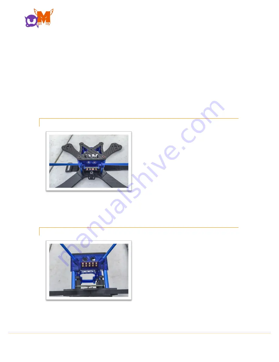
The final step in the frame assembly is the
installation of the
LED Board
(A) and the
Antenna tubes into the
Receiver, VTX,
LED and Antenna Tray
(K).
The LEDs supplied with your Wyvern 200
are rated to 12V and need to be connected
to the 12V output pad on the
PDB
(B).
The installation of the LED Board (A) is
tight and it will have to be pressed into location to seat properly; this tight fit is by
design as only this friction fit holds the
LED Board
(A) in place. It is easier to
Summary of Contents for Wyvern 200
Page 1: ...WYVERN 200 ASSEMBLY GUIDE...


