2
Installation Instructions
Quad Power Brush
86348
B
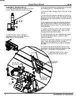
LOCATION
SCALE 1 : 6
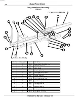
DETAIL B
PIN MOUNT
LIFT PIN
CARRIAGE BOLT
CENTER SHROUD
EXISTING LIFT
ACTUATOR
TRUNNION PIN
2. Slide trunnion mount to achieve
dimension shown. Secure in place by
tightening the clamping bolts.
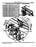
Installation - Electrical Pivot
1. Loosen clamping bolts on actuator trunnion
mount. Make sure both bolts are loose.
3. Remove the lift pin from existing mount location
by removing 1/4 x 1-1/4 bolts and nuts.
4. Remove center carriage bolt from the top of the
shroud.
5. Place new lift extension brackets over existing
lift pin mount so that the center hole aligns with the
center hole on the shroud where you just removed
the bolt from.
6. Re-install bolt securing lift extension bracket to
shroud using a 9/32" drill bit. Drill 2 holes in the
shroud flange and two holes in the existing lift pin
mount bracket.
7. Install 1/4 x 3/4 hex bolts in the rear locations
and secure with 1/4" flange nuts. Use 1/4 x 3/4
carriage bolts in the front location.
8. Bolt the actuator rod mount bracket (4) to gear
box pivot bracket as shown, using four 3/8 x 1
bolts, lockwashers.
9. Place two 1/2" SAE washers on top of gear box
plate. Align with holes as shown. Position
actuator trunnion pins through washers and gear
box plate.
10. Position actuator base bracket (3) over top
trunnion pin and secure bracket to gear box plate
using 3/8 x 1 hex bolts and lockwashers.
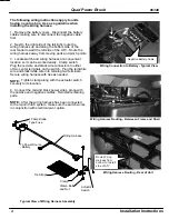
11. Install switch kit on ATV using
instructions from the switch kit.
64 2.5


