background image

March 28, 2012

7037-141B

Page  9

R

2100 & 4300 Millennium ACC Wood Burner


PIONEER DOUBLE FLUE SHIELD FITTING INSTRUCTIONS


1.QF.1G


1. Unpack the Flue Mounted Shield, detach the three brackets and familarize yourself with the


illustrations.


2. Using a sharp knife or razor blade, carefully cut through the plastic film on the “inside face” where 

it meets the outer shield (refer sketch). Cut along the full length of the Flue Mounted Shield on 

both side, then peel off and fully remove the plastic film from the stainless steel inner shield.


3. Peel back and fully remove the plastic film from the outer shield.


4. Fit the top bracket to the Flue Mounted Shield as illustrated ensuring the rear mid section of the 

bracket fits “outside” while the two outer sections of the bracket fit “inside”.


5. Fit the appropriate lower bracket to your woodfire.


Lower Bracket “5B suitable for all other woodfires without an inner rear heatshield. 

On certain model woodfires without a raised flue spigot it will be necessary to cut off both the 

lower outer legs from the bracket “5B” leaving the entral tongue to locate inside the flue outlet 

only.


Two tabs are provided and if folded back at 90 degrees the bracket and Flue Mounted Shield will 

mount lower onto the appliance.


The Flue Mounted Shield then locates into the two notches provided n bracket “5B” as illustated.


6. Once the Flue Mounted Shield is fitted in position onto either of the two lower mounting brackets, 

check to ensure a large gap is not present between the top of the woodfire and the base of the 

Flue Mounted Shield, as this may result in a hot spot on the rear wall directly behind the flue 

outlet. If your woodfire has a lift off top grill the Flue Mounted Shield should be raised sufficiently 

to enable the top grill to be removed.


7. Using the pre-punched holes in the two tabs provided on the top bracket as guides, drill into the 

flue pipe and secure the top bracket to the flue pipe with two stainless steel rivets (not supplied).


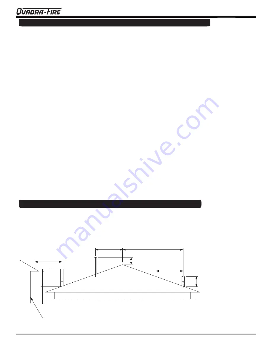
MINIMUM HEIGHT OF FLUE SYSTEM EXIT


As per AS/NZS 2918:2001 4.9.1 Fig 4.9


Fig. 8


3000


3000 

or less


More than 3000


600 min.


3000


increase from 1000mm 

minimum until clear within


3000mm of flue top


increase as necessary 

until nothing within


3000mm of flue top


Any nearby structure


Summary of Contents for 21M-ACC-NZ

Page 1: ...a ceiling angle greater than 30 refer to Fig 6 7 and AS NZS 2918 2001 4 6 3 b Ceiling Plate may vary in size depending on ceiling angle Please specify ceiling pitch prior to ordering the ceiling plate...

Page 2: ...mm 660mm 247mm 330mm C L 292mm 527mm 406mm C L L C 729mm 668mm 170mm 108mm Outside Air Connection Fig 2 Quadra Fire 4300 Millenium ACC Wood Burner Dimensions roomfor 14x 875 S N 1 5 x 375BarcodeLabel...

Page 3: ...ONFACTORBURNINGSOFTWOOD WHENTESTEDINACCORDANCEWITHAS NZS4013 MAXIMUMAVERAGEHEATOUTPUTBURNINGSOFTWOOD APPROVEDFUEL WETBACK ALLMODELS MANUFACTUREDBY PERFORMANCEMAYVARYFROMTESTVALUESDEPENDINGONACTUAL OPE...

Page 4: ...0 4300 A Min clearance from firebox to rear wall 150 200 B Min clearance from firebox to side wall 550 400 C Min distance from firebox opening to floor protector front 300 300 D Min distance from fire...

Page 5: ...is being used position now Place the firebox on the floor protector to suit the minimum installation clearances See Fig 3 or 4 2 Seismically restrain the firebox and the floor protector to the floor...

Page 6: ...t roof penetration see NZ Building Code E2 Acceptable Solution from 01 07 05 5 Install the outer casing so that i lower end is flush with the underside of the ceiling material and ii with the addition...

Page 7: ...sing cover is necessary minimum 25mm gap between flue pipe casing combustible material Non combustible material Hebel block or 12mm Promina board or similar under the flashing 25 25 Approved Flashing...

Page 8: ...b Fig 4 6 downward distance of casing and 3 x flue distance of the ceiling plate ADD Cowl Casing Cover Spider Bracket Approved Flashing A Ceiling Plate Batten A 3 x flue pipe Ceiling flue pipe Fig 7...

Page 9: ...legs from the bracket 5B leaving the entral tongue to locate inside the flue outlet only Two tabs are provided and if folded back at 90 degrees the bracket and Flue Mounted Shield will mount lower ont...

Page 10: ...MANUFACTURER SHOULD BE CONSULTED IN THE FIRST INSTANCE CAUTIONS CRACKED AND BROKEN COMPONENTS e g GLASS PANELS OR CERAMIC TILES MAY RENDER THE INSTALLATION UNSAFE WARNING ANY MODIFICATION OF THE APPLI...

Page 11: ...March 28 2012 7037 141B Page 11 R 2100 4300 Millennium ACC Wood Burner Homeowner Notes...

Page 12: ...Page 12 7037 141B March 28 2012 R 2100 4300 Millennium ACC Wood Burner Service And Maintenance Log Date of Service Performed By Description of Service...

Page 13: ...ACC STOVE DO NOT DISCARD THIS MANUAL CAUTION Important operating and maintenance instruc tions included Leave this manual with party responsible for use and operation Read understand and follow these...

Reviews: