background image

Page  16

7039-131H

May 5, 2011

R

2100 Millennium Wood Stove  (ACC)

Chimney Height / Rise and Run

This product was designed for and tested on a 6 inch (152mm) 

chimney, 14 to 16 feet (420-480cm) high, (includes stove 

height) measured from the base of the appliance.  The further 

your stack height or diameter varies from this configuration, 

the possibility of performance problems exists. 
Chimney height may need to be increased by 2 - 3% per 

each 1000 feet above sea level.  It is not recommended to 

use offsets or elbows at altitudes above 4000 feet above sea 

level or when there are other factors that affect flue draft.

C. Installing Chimney Components

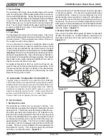
Chimney Connector

Single wall connector or stove pipe.  
This must be at least 24 gauge mild steel or 26 gauge blue 

steel.  The sections must be attached to the appliance and to 

each other with the crimped (male) end pointing toward the 

stove.  All joints, including the connection at the flue collar, 

should be secured with 3 sheet metal screws.  Make sure 

to follow the minimum clearances to combustibles.   Where 

passage through the wall, or partition of combustible con-

struction is desired in Canada, the installation shall conform 

to CAN/CSA-B365.
Factory-built listed chimney connector (vented).
A listed connector (vented) must be used when installing this 

unit in a mobile home.  The listed connectors must conform 

to each other to ensure a proper fit and seal.

Flue Gas 

Direction 

Crimped 

End 

Toward 

Stove 

Secure pipe sections with a 

minimum of 3 screws 

Figure 16.2   Chimney Connector  (Stove Pipe)

WARNING

•  DO NOT CONNECT THIS UNIT TO A CHIM-

NEY FLUE SERVICING ANOTHER APPLI-

ANCE.

•  DO NOT CONNECT TO ANY AIR DISTRI-

BUTION DUCT OR SYSTEM.

May allow flue gases to enter the house.

Asphyxiation Risk.

Improper installation, adjustment, alteration, service or 

maintenance can cause injury or property damage. Refer 

to the owner’s information manual provided with this appli-

ance. For assistance or additional information consult a 

qualified installer, service agency or your dealer.

WARNING

Fire Risk

.

Inspection of Chimney:
•  Chimney must be in good condition.
•  Meets minimum standard of NFPA 211
•  Factory-built chimney must be 6 inch 

(152mm) UL103 HT.

WARNING

WARNING

ONLY use connector:

•  Within the room, between appliance and ceiling or wall.

Connector shall NOT pass through:

•  Attic or roof space

•  Closet or similar concealed space

•  Floor or ceiling

Maintain minimum clearances to combustibles

Fire Risk.

Follow Chimney Connector Manufacturer’s 

Instructions for Proper Installation.

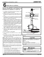
Chimney Flue 

Liner 

Fireclay 

Liner or 

Equivalent 

Masonry Chimney 

Constructed to NFPA 211 

Wall Spacer 

Wall Band 

Trim Collar 

Chimney 

 Connector 

1 inch (25mm) Air 

Space to Chimney 

Section 

Min. Clearance 

2 inch (51mm) 

Min. Chimney Clearance to 

Wall Spacer and 

Combustibles - 2 inch (51mm) 

Chimney Section 

Figure 16.1

Solid Pack Chimney with Metal Supports as a 

Thimble (Cont’d)

Summary of Contents for 21M-ACC

Page 1: ...nces to combustibles as specified Failure to comply may cause house fire Fire Risk WARNING For use with solid wood fuel only Other fuels may overfire and generate poisonous gases i e carbon monoxide I...

Page 2: ...ued steel connector pipe with a listed factory built UL103HT Class A chimney suitable for use with solid fuels or a masonry chimney and the referenced clearances DOUBLE WALL Six inch 6 inches 152mm di...

Page 3: ...ance 20 B Wood Selection Storage 20 C Burning Process 20 21 D Automatic Combustion Control ACC 21 E Air Controls 21 22 F Burn Rates Operating Efficiency 22 G Building A Fire 23 H Correct Baffle Blanke...

Page 4: ...e right to alter its products their specifications and or price without notice Improper installation adjustment alteration service or maintenance can cause injury or property damage For assistance or...

Page 5: ...isting of at least two escape routes 4 A plan to deal with a chimney fire as follows In the event of a chimney fire a Evacuate the house immediately b Notify fire department WARNING DO NOT CONNECT THI...

Page 6: ...include Exhaust fans kitchen bath etc Range hoods Combustion air requirements for furnaces water heaters and other combustion appliances Clothes dryers Location of return air vents to furnace or air c...

Page 7: ...ove the top of the appliance after one hour of operation at each burn setting NOTE These are guidelines only and may vary somewhat for individual installations F Tools And Supplies Needed Before begin...

Page 8: ...ermination Cap Outside Air Rear Vent Spark Arrestor Cap Floor Protector Chimney Connector Ceiling Support Listed Chimney Listed Termination Cap Storm Collar Flashing Figure 8 3 Interior Prefabricated...

Page 9: ...m 16 in 406mm 11 1 2 in 292mm 20 3 4 in 527mm C L C L 4 1 2 in 108mm Outside Air Connection A Appliance Dimensions Figure 9 1 Front View Figure 9 2 Side View NOTE Flue Collar size is 6 inch 152mm diam...

Page 10: ...by the regulatory authority having jurisdiction Fire Risk Comply with all minimum clearances to combustibles as specified Failure to comply may cause house fire WARNING NOTE Service Space In order to...

Page 11: ...39 in minimum 2 9 5 8 i n 2 5 3 8 i n 32 7 8 in 3 9 i n 3 in 1 3 5 o p t i o n a l c o v e r a g e 50 3 4 in Must extend 2 in 51mm beyond each side of pipe shaded area 203mm 8 in 203mm 8 in 203mm 8 in...

Page 12: ...sary in order for combus tion to take place Whatever combustion air is consumed by the fire must be replaced Air is replaced via air leakage around windows and under doors In homes that have tightly s...

Page 13: ...he bottom left rear corner as shown in Figure 13 1 See page 25 for detailed operating instructions for the blower and snap disc Figure 13 1 Shock Risk Do NOT remove grounding prong from plug Plug dire...

Page 14: ...teel black or 26 gauge blued steel or an approved air insulated double wall venting pipe Thimble A manufactured or site constructed device installed in combustible walls through which the chimney conn...

Page 15: ...ming lumber to fit into wall opening Inside opening of frame should be no less than 14 inch x 14 inch 356mm x 356mm Figure 15 1 4 Attach the wall spacer to the chimney side of the frame 5 Nail the fra...

Page 16: ...ors must conform to each other to ensure a proper fit and seal Flue Gas Direction Crimped End Toward Stove Secure pipe sections with a minimum of 3 screws Figure 16 2 Chimney Connector Stove Pipe WARN...

Page 17: ...roof within 10 feet 305cm Must be located away from trees or other struc tures These are safety requirements and are not meant to assure proper flue draft Figure 17 1 E 2 10 3 Rule Figure 17 2 NOTE C...

Page 18: ...anufacturer s instructions when installing the flue system for use in a mobile home 7 Maintain clearance to combustibles 8 Floor protection requirements must be followed precisely 9 Use silicone to cr...

Page 19: ...ire further adjustment B Adjusting The Blower Speed Control A Door Handle Assembly 1 Install washer on door handle shaft 2 Slide door handle through door 3 Install second washer s as shown in Figure 1...

Page 20: ...establishing the flue draft not evaporating the moisture out of wet unseasoned wood resulting in wasted heat Do not over fire Over firing may ignite creosote or will damage the stove and chimney To p...

Page 21: ...is function is performed by sliding the con trol all the way back until it stops at the HI indicator on the label and then pulling forward to the front of the stove until it stops This activates the A...

Page 22: ...is air is regulated by the Burn RateAir Control There are four settings High Medium High Medium Low and Low When the control is raised all the way up it is on the High setting and when pushed all the...

Page 23: ...ther the fire Stack the pieces of wood carefully near enough to keep each other hot but far enough away from each other to allow adequate air flow between them 7 Set the Burn Rate Air Control and acti...

Page 24: ...ement and replace baffle com ponents if damaged or missing H Correct Baffle Blanket Placement Ceramic Blanket and Baffle Board are NOT in contact with the back of the firebox Ceramic Blanket is NOT in...

Page 25: ...the snap disc with the manual over ride knob See page 13 2 The blower is equipped with a speed control Adjust the fan speed by turning the speed control clockwise to Low or counterclockwise to High 3...

Page 26: ...oise is caused by metal expanding and contracting as it heats up and cools down similar to the sound produced by a furnace or heating duct This noise does not affect the operation or longevity of the...

Page 27: ...lockage poor draft and chimney fires Always burn dry wood to help prevent cap blockage and creosote build up Keeping the door and glass gasket in good shape will maintain good burn times on a low burn...

Page 28: ...es Fire Risk Disposal of Ashes WARNING Ashes should be placed in metal container with tight fitting lid Do not place metal container on combustible surface Ashes should be retained in closed container...

Page 29: ...NOT OVERTIGHTEN 9 Replace the door on the appliance Quadra Fire stoves are equipped with ceramic super heat resistant glass which can only be broken by impact or misuse Do not slam stove door or impa...

Page 30: ...ottom bricks in unit 4 Install rear bricks on the top of the bottom bricks Slide top of bricks under clip on back of firebox wall and push bottom of brick back 5 Install side bricks Slide top of brick...

Page 31: ...first Figure 31 2 Place on top of baffle board open up and flatten and smooth out the blanket Re check the baffle board for correct positioning Figure 23 1 on page 23 and page 24 Figure 31 1 Baffle Fi...

Page 32: ...e tube channel assembly into side of firebox and insert each tube into the corresponding hole in the tube channel rack starting with the back hole first 3 Make sure tube channel assembly is flush agai...

Page 33: ...fire section Check for adequate vent height refer to chimney assembly section Open window below the appliance towards the wind Wood condition is too wet too large Use dry seasoned wood refer to wood f...

Page 34: ...od Stove ACC Service Parts 04 11 R 21M ACC Part number list on following pages 2100 Millennium Wood Stove Advanced Combustion Control ACC 1 2 3 4 5 6 7 8 9 10 11 12 14 16 15 13 Beginning Manufacturing...

Page 35: ...39 003 4 Brick Assembly Complete Set SRV7039 007 4 1 Brick 9 x 4 1 2 x 1 1 4 Qty 9 Req 4 2 Brick 6 x 4 1 2 x 1 1 4 Qty 3 Req 4 3 Brick 8 x 4 1 2 x 1 1 4 Qty 2 Req 4 4 Brick see diagram Qty 1 Req 4 5 B...

Page 36: ...ly 7033 034 Y 16 10 Door Gasket Front Rear Air Timer Doors 7033 282 Y 17 1 Door Assembly Black SRV7039 008 17 2 Hinge Pins 1 2 Gold 832 0250 Nickel 430 5320 Black 7000 606 2 17 3 Spring Handle 1 2 Nic...

Page 37: ...wer Assembly BK ACC Blower Control Box W Switch SRV7000 194 Y Blower Convection 812 4900 Y Component Pack 7033 051 Snap Disc Bracket Assembly 7033 036 Snap Disc 1 Convection Blower SRV230 0470 Y Wire...

Page 38: ...Page 38 7039 131H May 5 2011 R 2100 Millennium Wood Stove ACC Date of Service Performed By Description of Service C Service And Maintenance Log...

Page 39: ...May 5 2011 7039 131H Page 39 2100 Millennium Wood Stove ACC R C Service And Maintenance Log Cont d Date of Service Performed By Description of Service...

Page 40: ...Page 40 7039 131H May 5 2011 R 2100 Millennium Wood Stove ACC D Homeowner s Notes...

Page 41: ...May 5 2011 7039 131H Page 41 2100 Millennium Wood Stove ACC R D Homeowner s Notes...

Page 42: ...Page 42 7039 131H May 5 2011 R 2100 Millennium Wood Stove ACC E Warranty Policy...

Page 43: ...May 5 2011 7039 131H Page 43 2100 Millennium Wood Stove ACC R...

Page 44: ...45502 6170481 6237588 6296474 6374822 6413079 6439226 6484712 6543698 6550687 6601579 6672860 6688302B2 6715724B2 6729551 6736133 6748940 6748942 6769426 6774802 6796302 6840261 6848441 6863064 686620...

Reviews: