background image

CHIMNEY CONNECTOR

The chimney connector must be 6” (152mm) diameter with a minimum thickness of 24 gauge.  Do not use
aluminum or galvanized steel.  They cannot properly withstand the extreme temperatures of a wood fire.  Do not
use chimney connector pipe as a chimney.  You must connect your stove to a chimney comparable to those
illustrated in this manual.

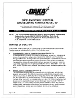
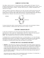
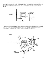
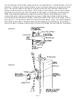
Chimney connector sections must be attached to the stove and to each other with the crimped end toward the
stove (Figure 3). This allows creosote to run into the stove and not onto the outside of the pipe.  Attach the
chimney connector to the flue collar with three sheet metal screws.  All joints should also be secured with three
sheet metal screws.  Otherwise, in the event of a creosote fire, the connector may vibrate apart.

For proper operation, the chimney connector should be as short as possible.  Horizontal lengths of chimney
connector should have a minimum upward slope from the stove of at least ¼” per foot.

CHIMNEY HEIGHT/DRAFT

To insure that your Quadra-Fire stove burns properly, the chimney draft (static pressure) should be
approximately 0.1” water column (W.C.) during a high burn and .04” W.C. during a low burn, measured 6”
(152mm) above the top of the stove after one hour of operation at each burn setting.
NOTE:  These are guidelines only, and may vary somewhat for individual installations.

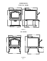
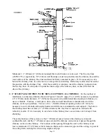
Your Quadra-Fire stove was designed for and tested on a 6” (152mm) chimney, 12’-14’ (3.66-4.27m) high,
measured from the top of the stove.  The further your stack height or diameter varies from this configuration,
the probability of performance problems increases.  In addition, exterior conditions such as roof line,
surrounding trees, prevailing winds and nearby hills can influence stove performance.

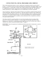
CONNECTION TO A MASONRY CHIMNEY

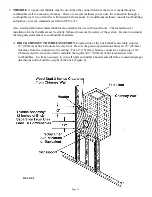
1.  CHIMNEY:  Should the stove be connected to a masonry chimney, the chimney should be examined for

cracks, loose mortar, or other signs of deterioration and blockage.  The stove should not be installed until it
is determined that the chimney is safe for use.  Since an oversized flue contributes to the accumulation of
creosote, the size of the flue should be checked to determine that it is not too large for the stove.  The
chimney should also be checked to insure it meets the minimum standards of the National Fire Protection
Association (NFPA) Standard 211.  Following is a list of the more critical minimum requirements for a
properly constructed chimney.

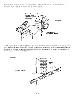
The masonry wall of the chimney, if brick or modular block, must be a minimum of 4” (102mm) thick.  A
mountain or rubble stone wall must be at least 12” (305mm) thick.

Page 8

FIGURE 3

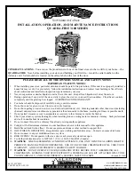
Summary of Contents for 3100 Series

Page 1: ...unit to a chimney flue already serving another appliance 10 Comply with all minimum clearances to combustibles as shown in this manual for this appliance 11 Build fire on brick firebox floor Do not us...

Page 2: ...h removal system installation 18 Ash removal system operating and cleaning 19 Operating instructions 20 Burning process 20 Primary and secondary air systems 20 Blower operating instructions 21 Operati...

Page 3: ...3100 SAFETY LABEL found on back of stove Page 3 Manufactaured by Model Quadra Fire 3100 Serial No...

Page 4: ...24 1 2 622mm 9 229mm 21 1 2 546mm 2 1 4 57mm 23 584mm DIMENSIONS Page 4 FIGURE 1b FIGURE 1a 20 1 2 521mm 9 229mm 24 1 2 622mm 2 1 4 57m m 23 584mm 26 3 8 670mm LEG MODEL PEDESTAL MODEL...

Page 5: ...m 4 5 16 110m m 24 5 8 626m m 25 635m m 9 229m m 2 13 16 72m m 21 1 2 546m m STEP TOP LEG MODEL 13 11 16 348m m 4 5 16 110m m 26 5 8 676m m 23 7 8 606m m 2 13 16 72m m 24 5 8 626m m 20 1 2 521m m 21...

Page 6: ...For installations with a preexisting class A chimney system a listed stainless steel chimney liner should be installed or the existing chimney examined by a chimney sweep for acceptable further use N...

Page 7: ...all at least one smoke detector on each floor of your home to ensure your safety They should be located away from the heating appliance and close to the sleeping areas Follow the smoke detector manufa...

Page 8: ...p of the stove after one hour of operation at each burn setting NOTE These are guidelines only and may vary somewhat for individual installations Your Quadra Fire stove was designed for and tested on...

Page 9: ...the spaces where the chimney passes through floors and or ceiling Figure 5 The chimney must have a fire clay flue liner or equivalent with a minimum thickness of 5 8 16mm and must be installed with r...

Page 10: ...hest point where it passes through the roof and at least 2 610mm higher than the highest part of the roof or structure that is within 10 3048mm of the chimney measured horizontally Figure 7 Remember t...

Page 11: ...imbles must be strictly followed to assure the safety of the system Be sure to maintain the designated clearances to combustible materials A BRICK CHIMNEY THIMBLE ASSEMBLY Construction of the brick th...

Page 12: ...mm long section of prefabricated listed solid pack chimney to use as a thimble Purchase a wall spacer trim collar and wall band that are manufactured to fit the chimney section you purchase Cut out a...

Page 13: ...eyond the edge of the chimney flue lining Apply high temperature furnace cement to the end of the chimney section and install it over the connector through the wall band and through the wall spacer Ti...

Page 14: ...ll an exterior chimney that runs up the outside of the residence Figure 13 This method of installation requires at a minimum a wall pass through device a wall support package insulated T section and r...

Page 15: ...ved grounding device 6 Refer to clearance to combustibles section page 6 for listing to combustibles 7 Seal all wall floor inlets to prevent air or moisture penetration Check periodically to insure th...

Page 16: ...w ash lip with two 20 mounting screws 2 Mount rear air intake cover plate with two mounting screws 3 Install each side cover with two 8 32 screws 4 Floor installation Cut a 3 76mm minimum hole in the...

Page 17: ...tective pad or pallet 3 Bolt cover piece onto mounting brackets using outer two mounting holes 4 Slip washers onto bolts then bolt legs onto mounting brackets 5 Screw leg assembly onto adapter on bott...

Page 18: ...ly stand stove up and place in desired location 8 Slip wooden decorative strips onto pedestal edges 9 Open door of stove and check to insure firebricks and kaowool blanket are in their proper location...

Page 19: ...stem grate into the drawer below If there are large pieces in the ashes you can remove the grate before cleaning the ash into the drawer Be sure to replace the grate before operating the stove 3 Relea...

Page 20: ...ained and not allowed to go out This will insure the cleanest possible fire If you are adjusting your stove for a low burn rate you should close down the air to the point where you can still maintain...

Page 21: ...um of 15 minutes 2 Regulate burn rate heat output by using the secondary control center under ashcatcher The primary control on the right is mainly for initial start up reloading or high burns 3 Heat...

Page 22: ...to allow adequate air flow between them 7 When ready to reload the stove add more logs Large logs burn slowly holding a fire longer Small logs burn fast and hot giving quick heat 8 Adjust the primary...

Page 23: ...on removable film on inside of glass Overfiring voids warranty NOTE Replace with ceramic glass only CARE AND CLEANING OF PLATED SURFACES Clean 24 karat gold plated surfaces with vinegar or a glass cle...

Page 24: ...rame pieces over the fiberglass tape on the edges of the glass Be sure glass is centered in the opening i e same space top and bottom left and right sides 6 Reinstall screws and glass tabs tight enoug...

Page 25: ...ve the firebrick from the sides of the stove 4 With a 3 16 allen wrench remove the secondary combustion tube retainer bolts on the secondary air channel under the end of each tube NOTE Soak the bolts...

Page 26: ...2 through 7 in reverse Be sure that the hole in the baffle is on its alignment pin on the rear shelf 7 Keep the baffle tilted as you lift it out the door BAFFLE REMOVAL AND INSTALLATION cont Page 26...

Page 27: ...r this unit is adjusted at the factory and should not require further adjustment When the speed control is turned clockwise it will click on to high speed Turn the speed control clockwise to decrease...

Page 28: ...S clips to the upper edge of the outer wall of the stove 3 Set top heat shield on stove and push down into S clips 4 Install chimney pipe through hole in top heat shield NOTE SEE PAGE 6 FOR REDUCED CL...

Page 29: ...32 1911 Trim door 832 0031 Gold door 831 1670 Ash removal system SERVICE PARTS 832 0420 Kaowool blanket 832 3010 Firebox brick set clay 3100 Unibody 3100 ARS 832 0550 Individual brick clay 832 0360 Ba...

Page 30: ...NOTES Page 30...

Page 31: ...NOTES Page 31...

Page 32: ...for any alteration to the unit which causes sooting that results in damage to the interior or exterior of the building in which this appliance is installed This warranty is void if the stove has been...

Reviews: