R
October 24, 2011
Page 23
Castile & Santa Fe CE Pellet Stove
7068-112B
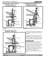
Vent Configurations
To reduce probability of reverse drafting during shut-down
conditions Hearth & Home Technologies strongly recom
-
mends:
• Installing the pellet vent with a minimum vertical run
of 1.52m. Preferably terminating above the roof line.
• Installing the outside air kit at least 1.22m below the
vent termination.
To prevent soot damage to exterior walls of the house and
to prevent re-entry of soot or ash into the house:
• Maintain specified clearances to windows, doors and
air inlets, including air conditioners.
• Vents should not be placed below ventilated soffits.
Run the vent above the roof.
• Avoid venting into alcove locations.
• Vents should not terminate under overhangs, decks
or onto covered porches.
• Maintain minimum clearance of 152mm from the vent
termination to the exterior wall. If you see deposits
developing on the wall, you may need to extend this
distance to accommodate your installation conditions.
Negative pressure results from the imbalance of air avail
-
able for the appliance to operate properly. It can be stron
-
gest in lower levels of the house.
Causes include:
• Exhaust fans (kitchen, bath, etc.)
• Range hoods
• Combustion air requirements for furnaces, water heaters
and other combustion appliances
• Clothes dryers
• Location of return-air vents to furnace or air conditioning
• Imbalances of the heating/cooling air handling system
• Upper level air leaks such as:
- Recessed lighting
- Attic hatch
- Duct leaks
WARNING! Risk of Asphyxiation!
Negative pressure can
cause spillage of combustion fumes and soot.
C. Negative Pressure
NOTICE:
Hearth & Home Technologies assumes no
responsibility for the improper performance of the chimney
system caused by:
• Inadequate draft due to environmental conditions
• Downdrafts
• Tight sealing construction of the structure
• Mechanical exhausting devices
D. Draft
To minimize the effects of negative air pressure:
• Install the outside air kit with the intake facing prevailing
winds during the heating season
• Ensure adequate outdoor air for all combustion appliances
and exhaust equipment
• Ensure furnace and air conditioning return vents are not
located in the immediate vicinity of the appliance
• Avoid installing the appliance near doors, walkways or
small isolated spaces
• Recessed lighting should be a “sealed can” design
• Attic hatches weather stripped or sealed
• Attic mounted duct work and air handler joints and seams
taped or sealed
On nominal heat output the combustion blower operates at
2053 rpm developing 0.33 m^3/s. This is the minimum require
-
ment for the supply of combustion air.
Draft is the pressure difference needed to vent appliances
successfully. When an appliance is drafting successfully, all
combustion byproducts are exiting the home through the
chimney.
Install through the warm airspace enclosed by the building
envelope. This helps to produce more draft, especially dur
-
ing lighting and die-down of the fire.
Considerations for successful draft include:
• Preventing negative pressure
• Location of appliance and chimney
To measure the draft or negative pressure on your appliance
use a magnahelic or a digital pressure gauge capable of
reading 0 - .13mm of water column (W.C.).
The appliance should be running on high for at least 15
minutes for the test.
With the stove running on high you should have a negative
pressure equal to or greater than the number given in the
chart below. If you have a lower reading than you find on the
chart, your appliance does not have adequate draft to burn
the fuel properly.
Minimum Vacuum Requirements:
.095

