background image

18

June 4, 2019

7027-801C

CB1200 Free Standing

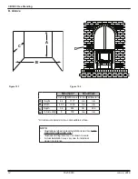
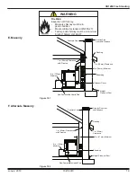
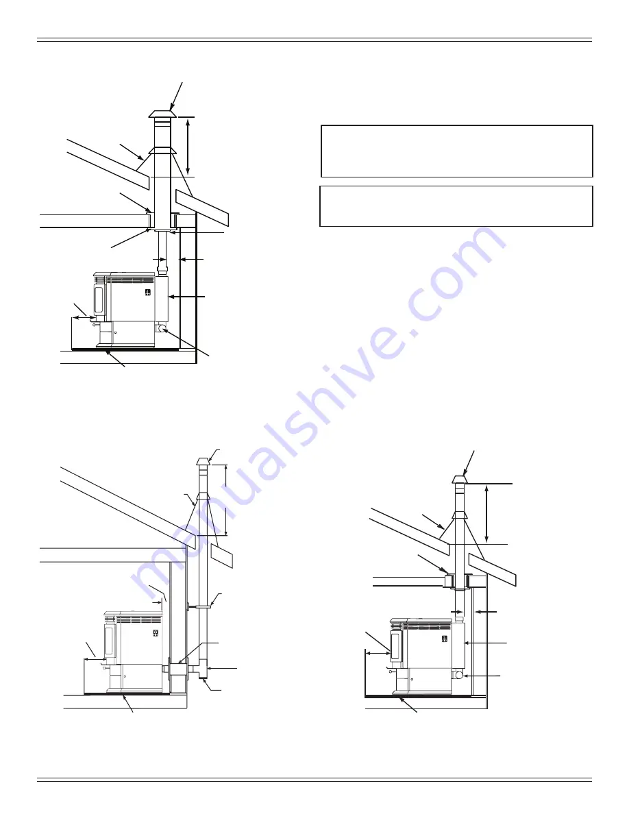
C. Through The Wall & Vertical - Exterior

Figure 18.1

Figure 18.2

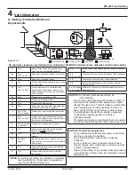
D. Vertical - Interior - Typical Installation

Figure 18.3

Firestop

Flashing

Rain Cap

6 in.

(152mm)

Min.

Non-combustible Hearth Pad

3 in. (76mm)

Min.

Clean-out

Cover

12 in. (305mm)

minimum

Ceiling Support

Class A Chimney

Connector Adapter

Top Vent Kit

Non-combustible Hearth Pad

Clean-out Cover

Tee 

Wall Thimble 

Support Bracket 

every 60 in. (1524mm) 

12 in. (305mm) 

Minimum 

Rain Cap 

Flashing 

2 in. (51mm) Minimum 

6 in. (152mm) 

Minimum 

Firestop

Flashing

Rain Cap

6 in. 

(152mm) 

Min.

Non-combustible Hearth Pad

3 in. (76mm)


Min.

12 in. 

(305mm)


Minimum

3 in. to 3 in. 

(76-76mm) 

Top Vent Kit

Clean-out Cover 

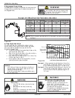
All three installations are approved for mobile home 

installations. Must use 3 or 4 inch (76 to 102mm) “L” or “PL” 

Listed pellet venting or Listed double wall pipe and Quadra-

Fire Outside Air Kit  in mobile homes. Single wall pipe is 

approved for residential installations only.

B. Vertical into Existing Class A Chimney

*NOTE:

 Clearance to combustibles are for standard 

pellet pipe. If pellet pipe manufacturer allows 

reduced clearances to their pipe, reduced 

clearances are allowed.

NOTE:

 A chimney connector shall not pass through an 

attic or roof space, closet or similar concealed 

space, or a floor or ceiling.

Summary of Contents for CLASSIC BAY 1200

Page 1: ...causing property damage personal injury or death WARNING Do not store or use gasoline or other flammable vapors and liquids in the vicinity of this or any other appliance Do not over fire If appliance...

Page 2: ...ons 5 B Thermostat Wall Control Location 6 C Tools And Supplies Needed 6 D Inspect Appliance and Components 6 E Install Checklist 7 3 Dimensions and Clearances 8 A Appliance Dimensions 8 B Clearances...

Page 3: ...rage HHV High Heating Value efficiency using data collected during EPA emissions tests A range of BTU outputs calculated using HHV efficiency and the burn rates from the EPA tests Based on the maximum...

Page 4: ...ock drywall Any material that can ignite and burn flame proofed or not plastered or non plastered H Sleeping Room When installed in a sleeping room it is recommended that 3ft of vertical be installed...

Page 5: ...rts could impair safe operation Do NOT install damaged incomplete or substitute components NOTICE Check building codes prior to installation Installation MUST comply with local regional state and nati...

Page 6: ...ce and remove all the parts and articles packed inside the Component Pack Inspect all the parts and glass for shipping damage Report to your dealer any parts damaged in shipment All labels have been r...

Page 7: ...ion and copying this checklist for your file That this checklist remain visible at all times on the appliance until the installation is complete Electrical 120 VAC unswitched power provided to the app...

Page 8: ...21 1 4 539 10 3 8 264 2 3 8 62 3 5 8 94 5 127 14 1 4 362 33 3 8 847 31 1 4 795 2 3 8 62 2 3 4 69 5 127 14 1 4 362 Figure 8 4 Top View with Top Vent Adapter TPVNT 1 and Offset Adapter 812 3570 Figure...

Page 9: ...w with Top Vent Adapter TPVNT 1 and Offset Adapter 811 0720 2 3 8 62 2 3 4 69 3 7 8 100 6 1 4 159 8 203 8 203 Figure 9 2 Top View with Top Vent Adapter TPVNT 6 and Offset Adapter 811 0720 15 51 8 398...

Page 10: ...trations diagrams are not drawn to scale Actual installation may vary due to individual design preference Horizontal Through the Wall Inches Millimeters A Back Wall to Appliance 2 51 B Side Wall to Ap...

Page 11: ...pe shaded area to the wall thimble CANADA 47 3 4 in 26 1 4 in 21 1 2 in 41 3 8 in 6 in from the fuel door opening USA 1214mm 666mm 545mm 1051mm 152mm front door opening CANADA Must extend 51mm beyond...

Page 12: ...m Maximum Inches Millimeters Inches Millimeters A Height 44 1117 n a n a B Width 40 5 1029 n a n a C Depth 36 914 36 914 D To Side Wall 6 152 n a n a NOTE Illustrations reflect typical installations a...

Page 13: ...es and protruding parts of the structure P 12 in Clearance above roof line for vertical terminations All minimum clearances are listed with an Outside Air Kit OAK installed unless otherwise noted in t...

Page 14: ...Vent Configurations When installing a pellet appliance with a horizontal vent configuration the frequency of power outages should be considered Power outages during operation will cause the appliance...

Page 15: ...seams taped or sealed E Chimney and Exhaust Connection 1 Chimney Connector Use 3 or 4 inch 76 102mm diameter type L or PL venting system It can be vented vertically or horizontally NOTE All pipe must...

Page 16: ...02mm diameter type L or PL vent G Pipe Selection Chart The chart will help you in determining proper venting size according to the equivalent feet of pipe calculated previously and the altitude above...

Page 17: ...d for mobile home installations Must use 3 or 4 inch 76 102mm L or PL Listed pellet venting or Listed double wall pipe and a Quadra Fire Outside Air Kit in mobile homes NOTE In Canada where passage th...

Page 18: ...Rain Cap 6 in 152mm Min Non combustible Hearth Pad 3 in 76mm Min 12 in 305mm Minimum 3 in to 3 in 76 76mm Top Vent Kit Clean out Cover All three installations are approved for mobile home installation...

Page 19: ...ce Concrete Cap 1 in 25mm Clearance with Firestop 6 in 152mm Minimum Non Combustible Hearth Pad Sheathing 2 in 51mm Minimum 1 in 25mm Clearance Flashing Fireclay Flue Liner withAirspace Concrete Cap 6...

Page 20: ...side termination cap with second hose clamp f Secure termination cap to outside surface g Secure trim ring to interior wall h Snip corners and remove plate Figure 20 1 i Align and secure collar assemb...

Page 21: ...ter Figure 21 3 Rear to Top Vent Adapter 90o Figure 21 1 C Rear Vent Rear Vent to Top Vent Adapter 1 Put a layer of high temp silicone on the 3 inch 76mm exhaust outlet 2 Slide the adapter onto the re...

Page 22: ...e the wires through the opening in the base plate and hold the base against the wall while aligning up to the holes Attach base plate using a Phillips head screwdriver and two screws 5 Connect your th...

Page 23: ...fire pot Figure 23 1 NOTE Due to the abrasive nature of a pellet appliance fire the logs are not covered under warranty Any placement variation other than shown here can cause excessive heat and shal...

Page 24: ...24 PART NUMBER 811 0872 Spark Arestor Cap Roof Flashing Storm Collar Joist Shield Firestop Double Wall Connector Pipe Figure 24 1 WARNING Products of combustion generate carbon monoxide and different...

Page 25: ...25 June 4 2019 7027 801C CB1200 Free Standing 8 Accessory List A Service Maintenance Log Date of Service Performed By Description of Service...

Page 26: ...crew 5 16 18 X 1 4 Pkg of 25 225 0550 25 Y 42 Deflector Air Left Curtain 410 4992 Component Pack SRV7127 017 Cleanout Tool 414 1140 Y Harness Thermostat Wire 230 0810 Paint Touch Up 4 oz 812 0910 Powe...

Page 27: ...SSORIES Collar Offset Top Vent 812 3570 Damper 3 Inch Tall Vertical Installs Only PEL DAMP3 Y Damper 4 Inch Tall Vertical Installs Only PEL DAMP4 Heat Exchange Repair Kit 812 4970 Log Set 811 0592 Out...

Page 28: ...purchased installed _________________________________________________________________________ Serial Number ____________________________________ Location on appliance ___________________________ Deale...

Reviews: