10/08
Page 17
Quadra-Fire • Columbia Bay • 250-5195 Rev. K
Step 7.
Continue to assemble pipe sections until the height of the
vent (before adding the termination cap) meets the minimum
code requirements as outlined in the current CAN/CGA-B149
Installation Codes (in Canada), the National Fuel Gas Code
NFPA 54/ANSI Z223.1 (in USA), or local codes. Note that
for steep roof pitches, the vent height must be increased.
See Roof Pitch Table (
Figure 4.3
, on page 8). In high wind
conditions, nearby trees adjoining rooflines, steep pitched
roofs, and other similar factors can result in poor draft, or
down drafting. In these cases increasing the vent height or
switching to the high wind termination cap may solve this
problem.
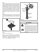
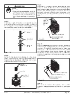
Step 8.
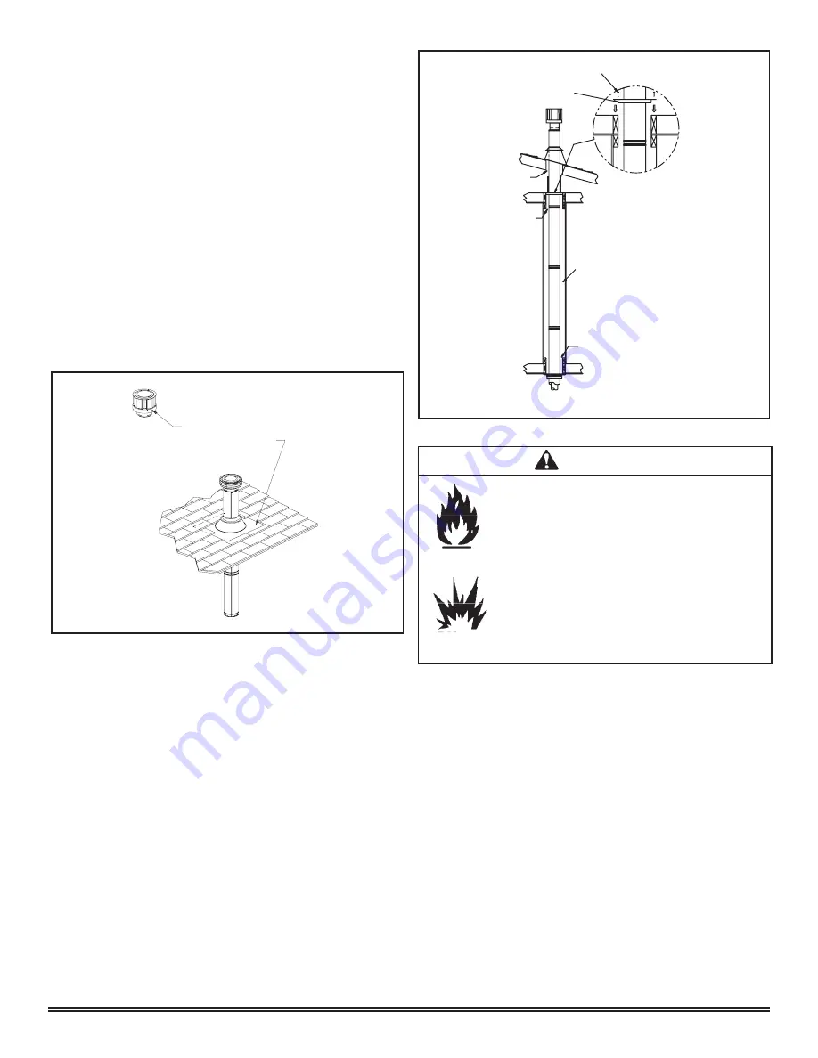
Slip the storm collar over the pipe, and push it down to the
top of the flashing (
Figure 5.16
). Use non-hardening sealant
above and below the joint between the storm collar and the
pipe.
OPTIONAL HIGH WIND
TERMINATION CAP
SECURE FLASHING WITH
NON-HARDENING SEALANT
AND ROOFING NAILS
Figure 5.16
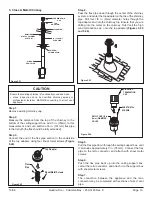
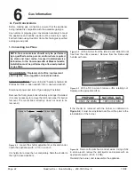
MIN. 1 in. (25mm)
CLEARANCE
CEILING FIRESTOP
NAILS
MIN. 1 in. (25mm)
CLEARANCE
MIN. 1 in. (25mm)
CLEARANCE
MIN. 1 in. (25mm)
CLEARANCE
Figure 5.17
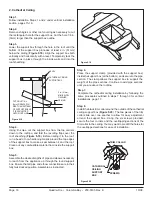
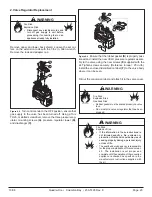
Fire Risk.
Explosion Risk.
WARNING
• Any occupied areas above the first floor, including
closets and storage spaces, which the vertical
vent passed through must be enclosed. The
enclosure may be framed and sheetrocked with
standard construction materials; however, refer
to these installation instructions for the minimum
allowable clearance between the outside of the
vent pipe and the combustible surfaces of the
enclosure. Do not fill any of the required air space
with insulation.
Step 9.
Twist-lock the vent cap and seal.
Note:
For multi-story vertical installations, a ceiling firestop
is required at the second floor, and any subsequent floors
(
Figure 5.17
). The opening should be framed to 10 in. x
10 in. (254mm x 254mm) inside dimensions, in the same
manner as shown in
Figure 5.14
, on page 16.


