background image

45

Quadra-Fire  •  Expression 36 (QV36A-FB)  •  2062-900  Rev. S  •  11/11

Initial Break-in Procedure

When you light the appliance, you may notice that it pro-
duces heat which does have an associated odor or smell. 
If you feel this odor is excessive it may require the initial 
three to four hour continuous burn on high followed by a 
second burn up to 12 hours to fully drive off any odor from 
paint and lubricants used in the manufacturing process. 
Condensation of the glass is normal.

Note:

 The appliance should be run three to four hours 

on the initial start-up. Turn it off and let it cool completely. 
Remove and clean the glass. Replace the glass and run 
the appliance for an additional 12 hours. This will help to 
cure the products used in the paint and logs.

During this break-in period it is recommended that some 
windows in the house be opened for air circulation. This will 
help avoid setting off smoke detectors, and help eliminate any 
odors associated with the appliance’s initial burning.

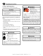
C.  After Appliance is Lit

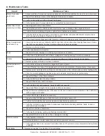
D. Frequently Asked Questions

Fire Risk.

High Temperatures.

Keep combustible household items away from 
appliance.

Do NOT obstruct combustion and ventilation air.

•  Do NOT place combustible items on top of or 

in front of  appliance. 

•  Keep furniture, draperies away from 

appliance.

Smoke and odors released during initial operation.

•  Open windows for air circulation.
•  Leave room during initial operation.
•  Smoke may set off smoke detectors.

Smoke and odors may be irritating to sensitive 
individuals.

CAUTION

•  Prevent accidental appliance operation when not 

attended. 

•  Unplug or remove batteries from remote control if absent 

or if appliance will not be used for an extended period of 
time.

•  Property damage possible from elevated temperatures.

CAUTION

Fire Hazard.

Keep combustible materials, gasoline and 
other  fl ammable vapors and liquids clear of 
appliance.

•  Do NOT store fl ammable materials in the 

appliance’s vicinity.

•  Do NOT use gasoline, lantern fuel, kerosene, 

charcoal lighter  fl uid or similar liquids in this 
appliance.

•  Combustible materials may ignite.

ISSUE

SOLUTIONS

 Condensation on the glass

This is a result of gas combustion and temperature variations. As the appliance warms, this 
condensation will disappear.

 Blue fl ames

This is a result of normal operation and the fl ames will begin to yellow as the appliance is al-
lowed to burn for 20 to 40 minutes.

 Odor from appliance

When fi rst operated, this appliance may release an odor for the fi rst several hours. This is 
caused by the curing of the paint and the burning off of any oils remaining from manufactur-
ing. Odor may also be released from fi nishing materials and adhesives used around the 
appliance.

 Film on the glass

This is a normal result of the curing process of the paint and logs. Glass should be cleaned 
within 3 to 4 hours of initial burning to remove deposits left by oils from the manufacturing 
process. A non-abrasive cleaner such as gas fi replace glass cleaner may be necessary. See 
your dealer.

 Metallic noise

Noise is caused by metal expanding and contracting as it heats up and cools down, similar to 
the sound produced by a furnace or heating duct. This noise does not affect the operation or 
longevity of the appliance.

  Is it normal to see the pilot fl ame burn
  continually?

In an intermittent pilot ignition system (IPI), the pilot fl ame should turn off when appliance is 
turned off. Some optional control systems available with IPI models may allow pilot fl ame to 
remain lit.

WARNING

WARNING

Summary of Contents for Expression 36

Page 1: ...NOT DISCARD Important operating and maintenance instructions included Read understand and follow these instructions for safe installation and operation In the Commonwealth of Massachusetts installation must be performed by a licensed plumber or gas fitter See Table of Contents for location of additional Commonwealth of Massachusetts requirements R Para obtener un ejemplar en Español de este Manual...

Page 2: ...e Information Listing Label Information Location Gas and Electric Information Serial Number Type of Gas The model information regarding your specific appliance can be found on the rating plate usually located in the control area of the appliance Not for use with solid fuel Ne doit pas entre utilise avec un combustible solide This appliance must be installed in accordance with local codes if any if...

Page 3: ...Installing Non combustible Facing Material 22 8 Installing Vent Pipe A Assembly of Vent Sections 23 B Disassembly of Vent Sections 25 C Installing Heat Shield and Horizontal Termination Cap 26 D Installing Roof Flashing and Vertical Termination Cap 27 9 Gas Information A Fuel Conversions 29 B Gas Pressures 29 C Gas Connection 29 10 Electrical Information A Recommendation for Wire 31 B Connecting t...

Page 4: ...idered non combustible materials E Combustible Materials Specification Materials made of or surfaced with wood compressed paper plant fibers plastics or other material that can ig nite and burn whether flame proofed or not or whether plastered or unplastered shall be considered combustible materials F Electrical Codes NOTICE This appliance must be electrically wired and grounded in accordance with...

Page 5: ...led heating appliance or equipment The sign shall read in print size no less than one half 1 2 inch in size GAS VENT DIRECTLY BELOW KEEP CLEAR OF ALL OB STRUCTIONS Inspection The state or local gas inspector of the side wall horizon tally vented gas fueled equipment shall not approve the installation unless upon inspection the inspector ob serves carbon monoxide detectors and signage installed in ...

Page 6: ...ckaging The vent system components and trim doors are shipped in separate packages The gas logs may be packaged separately and must be field installed Report to your dealer any parts damaged in shipment particularly the condition of the glass Read all of the instructions before starting the insta llation Follow these instructions carefully during the installation to ensure maximum safety and benef...

Page 7: ...ight fracture lines or spider webbing on the surface of the material Cracks that are less than 1 32 in wide and less than 3 in long If cosmetically unacceptable such cracks may be repaired with the SRV PACK service kit See Service Parts List Cracks that are unacceptable Cracks greater than 1 32 in wide and 3 in long are at risk of growing Cracks that penetrate entirely through the firebrick materi...

Page 8: ... access Locate appliance away from traffic areas A Selecting Appliance Location When selecting a location for your appliance it is important to consider the required clearances to walls see figure 3 1 Figure 3 1 Appliance Locations Note For actual appliance dimensions refer to Sec tion 16 In addition to these framing dimensions also reference the following sections Clearances and Mantel Projection...

Page 9: ... inside a chase Construction of the chase may vary with the type of build ing These instructions are not substitutes for the require ments of local building codes Local building codes MUST be checked Chases should be constructed in the manner of all out side walls of the home to prevent cold air drafting prob lems The chase should not break the outside building envelope in any manner Walls ceiling...

Page 10: ... Ceiling Combustible Floor Combustible Flooring Behind Appliance Sides of Appliance Front of Appliance Inches 10 52 17 1 4 41 1 2 32 1 2 0 0 1 1 2 36 Millimeters 254 1321 438 1054 825 0 0 25 13 914 WALL STUD 3 IN NON COMBUSTIBLE ZONE IS DEFINED BY 3 INCHES ABOVE THE ELBOW FOR THE ENTIRE WIDTH AND DEPTH BEHIND THE FRONT HEADER OF THE FIREBOX Note Framing should be constructed of 2 X 4 lumber or hea...

Page 11: ...ultiple Vertical Termination Figure 4 2 specifies minimum vent heights for various pitched roofs See Figure 4 4 for specific clearances 3 foot minimum in snow regions HORIZONTAL OVERHANG VERTICAL WALL GAS DIRECT VENT TERMINATION CAP 12 X ROOF PITCH IS X 12 LOWEST DISCHARGE OPENING 2 FT MIN 20 INCHES MIN H MIN MINIMUM HEIGHT FROM ROOF TO LOWEST DISCHARGE OPENING Gas Wood or Fuel Oil Termination Cap...

Page 12: ...nches non vinyl sidewalls 12 inches vinyl sidewalls O 18 inches non vinyl soffit and overhang 42 inches vinyl soffit and overhang P 8 ft QMIN RMAX 1 cap 3 feet 2 x Q ACTUAL 2 caps 6 feet 1 x Q ACTUAL 3 caps 9 feet 2 3 x Q ACTUAL 4 caps 12 feet 1 2 x Q ACTUAL QMIN termination caps x 3 RMAX 2 termination caps x QACTUAL Covered Alcove Applications Spaces open only on one side and with an overhang Mea...

Page 13: ...igure 5 1 Figure 5 1 5 5 Vent Information and Diagrams A Vent Table Key The abbreviations listed in this vent table key are used in the vent diagrams C Measuring Standards Vertical and horizontal measurements listed in the vent diagrams were made using the following standards 1 Pipe measurements are shown using the effective length of pipe see Figure 5 2 2 Measurements are made from the appliance ...

Page 14: ... Maximum V1 H1 30 ft 9 1 m Maximum Fire Risk Explosion Risk Do NOT pack insulation or other combustibles between ceiling firestops ALWAYS maintain specified clearances around venting and firestop systems Install wall shield and ceiling firestops as specified Failure to keep insulation or other material away from vent pipe may cause fire WARNING V1 Minimum H1 H2 Maximum 1 ft 305 mm 3 ft 924 mm 2 1 ...

Page 15: ... 1 ft 6 in 3 ft 2 ft 6 in 6 ft 3 ft 6 in 9 ft 4 ft 10 ft 4 ft 6 in 12 ft 5 ft 6 in 15 ft 6 ft 6 in 18 ft 7 ft 6 in 21 ft HT 21 ft Max VT 40 ft Max VT HT 30 ft Max Note A section of vertical pipe 12 inches minimum MUST be installed prior to attaching a 90 elbow If the horizontal component is less than 5 feet then the total vent run can be extended to 40 feet ...

Page 16: ...he horizontal component is less than 5 feet then the total vent run can be extended to 40 feet VT Min HT Max 1 ft 6 in 3 ft 2 ft 6 in 6 ft 3 ft 6 in 9 ft 4 ft 10 ft 4 ft 6 in 12 ft 5 ft 6 in 15 ft 6 ft 6 in 18 ft 7 ft 6 in 21 ft HT 21 ft Max VT 40 ft Max VT HT 30 ft Max Note A section of vertical pipe 12 inches minimum MUST be installed prior to attaching a 90 elbow ...

Page 17: ... Min HT Max 1 ft 6 in 3 ft 2 ft 6 in 6 ft 3 ft 6 in 9 ft 4 ft 10 ft 4 ft 6 in 12 ft 5 ft 6 in 15 ft 6 ft 6 in 18 ft 7 ft 6 in 21 ft HT 21 ft Max VT 40 ft Max VT HT 30 ft Max Note A section of vertical pipe 12 inches minimum MUST be installed prior to attaching a 90 elbow If the horizontal component is less than 5 feet then the total vent run can be extended to 40 feet ...

Page 18: ...no heat shield is necessary If your local inspector requires the wall shield firestop on both sides then both wall shield firestops must have a heat shield attached to them Fire Risk Explosion Risk Maintain vent clearance to combustibles as specified Do not pack air space with insulation or other materials Failure to keep insulation or other materials away from vent pipe may cause fire Figure 6 1 ...

Page 19: ...ttic Shield Note An additional ceiling firestop is not required if attic shield is used Frame opening for attic shield Attic shield may be installed above or below ceiling see Figure 6 4 Secure with three fasteners on each side Fold tabs at top of attic shield in toward vent pipe Tabs must keep vent pipe centered within shield Field construct additional shield height if insulation is deeper than h...

Page 20: ...Zone Cover Plate to the top of the appliance Figure 7 1 Remove Screws 2 Bend the four pre cut tabs up to expose the top of the appliance Place the Heat Zone cover plate on the insulation inside the unit centered between the three pre cut tabs that are the same size as shown in Figure 7 2 Use the Heat Zone cover plate as a template and cut around it carefully with a utility knife CAUTION Sharp Edge...

Page 21: ...aintain specified clearances around the appliance Do NOT notch into the framing around the appliance spacers Failure to keep insulation framing or other material away from the appliance may cause fire Fire Risk Prevent contact with sagging loose insulation Do NOT install against combustible materials such as exposed insulation plastic and insulation backer WARNING WARNING Figure 7 8 Proper positio...
Page 22: ... Figure 7 9 Attaching Non combustible Facing Material D Installing Non combustible Facing Material Center and attach two top boards to the framing members See Figure 7 10 Use fasteners from fastener packet in manual bag in shaded areas Use regular sheetrock screws in non shaded areas Use a wet or dry towel or soft brush to remove dust or dirt from facing material Apply a non combustible adhesive t...

Page 23: ...and the seams are not aligned see Figure 8 5 Tug slightly on sectionAto confirm it has completely locked into place It is acceptable to use screws no longer than 1 inch to hold outer pipe sections together If predrilling holes do NOT penetrate inner pipe For 90 and 45 elbows that are changing the vent direction from horizontal to vertical one screw minimum should be put in the outer flue at the ho...

Page 24: ...e slip section is too long the inner and outer flues of the slip section can be cut to the desired length Assembling Minimum Installations MI Sections MI sections are non unitized so that they can be cut to a certain length Cut these sections to length from the non expanded end see Figure 8 6 They can then be attached by first connecting the expanded end of the MI inner flue with the inner pipe fr...

Page 25: ...paced 120 apart may be used to do this see Figure 8 9 Horizontal Sections Horizontal sections of vent must be supported every 5 feet with a vent support or plumber s strap Figure 8 9 Securing Vertical Pipe Sections Figure 8 12 Align and Disassemble Vent Sections Figure 8 11 Rotate Seams for Disassembly Figure 8 10 Securing Horizontal Pipe Sections Improper support may allow vent to sag or separate...

Page 26: ...tion codes Figure 8 13 Venting through the Wall Burn Risk Local codes may require installation of a cap shield to prevent anything or anyone from touching the hot cap Fire Hazard Impaired performance of appliance Telescoping flue section of termination cap MUST be used when connecting pipe section to termination cap Maintain a 1 1 2 inch minimum overlap on telescoping flue section of termination c...

Page 27: ... burner operation HORIZONTAL OVERHANG VERTICAL WALL GAS DIRECT VENT TERMINATION CAP 12 X ROOF PITCH IS X 12 LOWEST DISCHARGE OPENING 2 FT MIN 20 INCHES MIN H MIN MINIMUM HEIGHT FROM ROOF TO LOWEST DISCHARGE OPENING Figure 8 15 WARNING TERMINATION CAP Figure 8 16 CAULK NOTICE Failure to properly caulk the roof flashing and pipe seams may permit entry of water Caulk the gap between the roof flashing...

Page 28: ...rm collar around the exposed pipe section and align brackets Insert a bolt provided through the brackets and tighten nut to complete storm collar assem bly see Figure 8 18 Slide the assembled storm collar down the pipe section until it rests on the roof flashing Caulk around the top of the storm collar see Figure 8 15 Assembling and Installing Storm Collar CAUTION Sharp Edges Wear protective glove...

Page 29: ...rfire condition Low pressure may cause explosion Verify minimum pressures when other household gas appliances are operating Install regulator upstream of valve if line pressure is greater than 1 2 psig 9 9 Gas Information Note Gas line may be run from either side of the appliance provided the hole in the outer wrap does NOT exceed 2 1 2 inches in diameter and does not penetrate the firebox Note A ...

Page 30: ...heck with local authorities Ensure that gas line does not come in contact with outer wrap of appliance Follow local codes Incoming gas line should be piped into the valve compartment and connected to the 1 2 inch connection on the manual shutoff valve CHECK FOR GAS LEAKS Explosion Risk Fire Risk Asphyxiation Risk Check all fittings and connections Do not use open flame After the gas line installat...

Page 31: ...reconstruction The battery pack requires two D cell batteries not includ ed Batteries cannot be placed in the battery pack while using the 3 volt AC transformer Conversely the trans former must be unplugged if the battery pack is used CAUTION Battery polarity must be correct or module damage will occur WARNING Figure 10 1 IntelliFire Pilot Ignition IPI Wiring Diagram Note 1 Ignition module valve p...

Page 32: ... 110 120 VAC source for added features the fireplace may have installed Electrical ratings for the control box are 110 VAC 60 Hz and is required for operation of this device Installation precautions Thisremoteistestedandsafewheninstalledinaccordance with this installation manual It is your responsibility to read all instructions before starting installation and to follow these instructions careful...

Page 33: ...ch Once a location is chosen and the electrical box is installed proceed as follows Install the provided control wire from the fireplace to the switch location Use caution not to stress the wire around tight or sharp corners Do not run the control wire adjacent to existing or future phone data cable or electrical lines The wire should not come into contact with any part of the fireplace exterior w...

Page 34: ...place at 20 F over set point and turn it back on at 20 F below set point Up and Down Arrows Push to adjust set point temperature under automatic control AUX Auxiliary Button Button Press Turns on auxiliary power Button Press Turns off auxiliary power Can be operated independently of all functions Child Proof Mode To Enter Child Proof Mode Press the UpArrow Button twice and DownArrow Button once Th...

Page 35: ...ctions and reattach the cover plate to the outer shell If the box is being wired from the INSIDE of the appliance Remove the screw attaching the junction box receptacle to the outer shell rotate the junction box inward to disengage it from the outer shell see Figure 10 6 Pull the electrical wires from outside the appliance through this opening into the valve compartment Feed the necessary length o...

Page 36: ...s must not interfere with Air flow through grilles or louvers Operation of louvers or doors Access for service 14 IN 23 IN 12 IN MIN 18 IN MIN 12 IN MAX 1 IN MAX 3 IN MIN Risk of Fire Non combustible clearances MUST be maintained 18 1 4 in 463 mm 44 in 1117 mm NON COMBUSTIBLE ZONE 5 4 3 2 1 2 1 4 6 8 1 2 WARNING WARNING WARNING Facing Requirements This appliance requires the supplied non combustib...

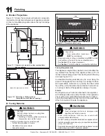
Page 37: ...cement instructions in manual Do NOT place embers directly over burner ports Replace ember material annually Improperly placed embers interferes with proper burner operation Placing the Ember Material Ember material is shipped with this gas appliance To place the ember material Embers CANNOT be placed directly over ports Care should be taken not to cover the lighting trail of ports from back to fr...

Page 38: ...AUTION Logs are fragile Figure 12 1 1 1 6 6 5 5 4 4 3 3 2 2 Carefully remove the grate from the foam sup ports and then remove the foam supports from around the burner Figure 12 2 Place grate on the base of the firebox surround ing the burner The grate should be centered on the burner and pushed back until it contacts the burner Figure 12 3 AIR BAFFLE ...

Page 39: ...that the bottom of the log conforms with the contour of the burner The outside of the log should rest on the grate The front of the log will rest against the right andiron LOG 1 SRV2062 701 Place log 1 on the back of burner Rest log on back of the grate The notches located on the bot tom of the log should rest over the back corners of burner Figure 12 4 Figure 12 5 Figure 12 6 1 1 1 1 2 2 2 2 1 1 ...

Page 40: ...n the bottom of log 6 should rest on the wedge shape on the end of log 3 LOG 5 SRV330 704 Place the Y end of log 5 against the corre sponding bump on log 3 The other end of the log should rest in the second smooth cut out area on top of log 1 LOG 4 SRV330 706 Nest log 4 in the cut out area on the right side of log 1 The thinnest arm of log 4 rests on top of log 2 2 2 3 3 4 4 1 1 2 2 3 3 4 4 5 5 1 ...

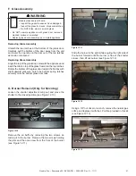
Page 41: ...the bottom of the glass door toward the firebox with slight upward pressure Latch the bottom spring latches securely onto the bottom glass door tabs G Burner Removal Only for Servicing Loosen the shutter adjustment wing nut and move the shutter to the closed position see Figure 12 10 Figure 12 10 Wing nut Wing nut Remove the air baffle by removing the two screws at taching it to the burner Remove ...

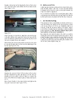
Page 42: ...ng the air shutter To adjust loosen the wing nut Care should be taken when adjusting the air shutter so as not to cause the appliance to soot If sooting occurs the air shutter will need to be opened by sliding the handle to the left When finished tighten wing nut Replace the burner by first tipping the front of the burner up to get the burner neck started into the shutter sleeve see Figure 12 14 O...

Page 43: ... replacement should be done by qualified technician Improper installation adjustment alteration service or maintenance can cause injury or property damage Refer to the owner s information manual provided with this appliance For assistance or additional information consult a qualified installer service agency or the gas supplier Do NOT use this appliance if any part has been under water Immediately...

Page 44: ...T TO DO IF YOU SMELL GAS DO NOT try to light any appliance DO NOT touch any electric switch do not use any phone in your building DO NOT CONNECT LINE VOLT AGE 110 120 VAC OR 220 240 VAC TO THE CONTROL VALVE Improper installation adjustment al teration service or maintenance can cause injury or property damage Re fer to the owner s information manual provided with this appliance This appliance need...

Page 45: ...ance will not be used for an extended period of time Property damage possible from elevated temperatures CAUTION Fire Hazard Keep combustible materials gasoline and other flammable vapors and liquids clear of appliance Do NOT store flammable materials in the appliance s vicinity Do NOT use gasoline lantern fuel kerosene charcoal lighter fluid or similar liquids in this appliance Combustible materi...

Page 46: ...gged into module Check voltage of transformer under load at spade connection on module with ON OFF switch in ON position Acceptable readings of a good transformer are between 3 2 and 2 8 volts AC b A shorted or loose connection in wir ing configuration or wiring harness Remove and reinstall the wiring harness that plugs into module Verify there is a tight fit Verify pilot assembly wiring to module...

Page 47: ...nuity with a multimeter with ohms set at lowest range e Faulty module Turn ON OFF rocker switch or wall switch to OFF posi tion Remove ignitor wire I from module Place ON OFF Rocker switch or wall switch in ON position Hold ground wire about 3 16 inch away from I terminal on module If there is no spark at I terminal module must be replaced If there is a spark at I terminal module is fine Inspect p...

Page 48: ...s Handle glass assembly with care Note Clean glass after initial 3 4 hours operation Longer operation without cleaning glass may cause a permanent white film on glass CAUTION When cleaning glass door Avoid striking scratching or slamming glass Do NOT use abrasive cleaners Use a hard water deposit glass cleaner on white film Do NOT clean glass when hot Turn off appliance after 3 4 hours of operatio...

Page 49: ...if firebox has been perforated Burner Ignition and Operation 1 Verify burner is properly secured and aligned with pilot or igniter 2 Clean off burner top inspect for plugged ports corrosion or deterioration Replace burner if necessary 3 Replace ember materials with new dime size and shape pieces Do not block ports or obstruct lighting paths 4 Check for smooth lighting and ignition carryover to all...

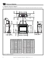
Page 50: ...mensions Use for reference only For framing dimensions and clearances refer to Section 3 Figure 16 1 Appliance Dimensions Location Inches Millimeters L 37 1 4 945 M 8 3 8 212 N 30 1 2 776 O 36 1 8 916 P 41 1043 Q 17 7 8 455 R 33 1 2 852 S 52 1321 T 2 1 4 56 U 5 126 V 34 1 2 876 Location Inches Millimeters A 17 1 4 437 B 1 24 C 31 3 8 798 D 16 1 4 413 E 9 3 8 238 F 8 202 G 20 1 2 521 H 53 3 4 1365 ...

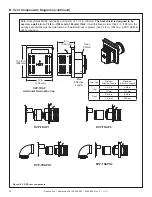
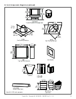
Page 51: ... 76 to 610 10 1 2 in 267 mm 10 7 8 in 276 mm 45 7 3 8 in 187 mm 11 3 8 in 289 mm 1 1 4 in 32 mm 9 1 4 in 235 mm 13 1 4 in 337 mm 1 2 in TYP DVP90ST 90 Elbow 10 in 254 mm 10 in 254 mm 1 in 25 mm 12 in 305 mm 14 in 356 mm 1 in 25 mm 8 in 203 mm 6 in 152 mm 10 in 254 mm 1 1 2 in 38 mm 5 in 127 mm 12 in 305 mm UP DVP HVS Vent Support DVP WS Wall Shield Firestop DVP FS Ceiling Firestop DVP45 45º Elbow ...

Page 52: ...eat shield is designed to be used on a wall 4 in to 7 1 4 in 102 mm to 184 mm thick If wall thickness is less than 4 in 102 mm the existing heat shields must be field trimmed If wall thickness is greater than 7 1 4 in 184 mm a DVP HSM B will be required Heat Shield B Vent Components Diagrams continued Figure 16 3 DVP vent components Term Cap Minimum Effective Length Maximum Effective Length Trap1 ...

Page 53: ...4 5 8 in 625 mm 13 1 4 in 367 mm RF12M Roof Flashing Multi pak BEK Trap Cap Brick Extension 13 3 4 in 349 mm 5 in 127 mm 13 3 4 in 349 mm Cap Shield DRC RADIUS 13 7 8 in 352 mm 9 1 2 in 241 mm 14 in 356 mm COOL ADD Cap Shield 11 5 8 in 295 mm 5 3 4 in 146 mm 7 1 8 in 181 mm 12 1 8 in 308 mm DVP TRAPFL DVP HSM B Extended Heat Shield 7 1 4 in 184 mm 5 1 4 in 133 mm 12 1 2 in 318 mm DVP TVHW Vertical...

Page 54: ...riginal purchase In the case of new home construction warranty coverage begins on the date of first occupancy of the dwelling or six months after the sale of the product by an independent authorized HHT dealer distributor whichever occurs earlier The warranty shall commence no later than 24 months following the date of product shipment from HHT regardless of the installation or occupancy date The ...

Page 55: ...XOW RI QRUPDO XVH V D KHDWLQJ DSSOLDQFH VRPH FKDQJHV LQ FRORU RI LQWHULRU DQG H WHULRU VXUIDFH ILQLVKHV PD RFFXU 7KLV LV QRW D IODZ DQG LV QRW FRYHUHG XQGHU ZDUUDQW DPDJH WR SULQWHG SODWHG RU HQDPHOHG VXUIDFHV FDXVHG E ILQJHUSULQWV DFFLGHQWV PLVXVH VFUDWFKHV PHOWHG LWHPV RU RWKHU H WHUQDO VRXUFHV DQG UHVLGXHV OHIW RQ WKH SODWHG VXUIDFHV IURP WKH XVH RI DEUDVLYH FOHDQHUV RU SROLVKHV 5HSDLU RU UHSOD...

Page 56: ...____________________________ ________________________________________________________________________________ ________________________________________________________________________________ ________________________________________________________________________________ ________________________________________________________________________________ DO NOT DISCARD THIS MANUAL CAUTION Leave this m...

Reviews: