background image

 2 


                        7080-162B 


           October 12, 2017

MT VERNON E2-C

TABLE OF CONTENTS

     Safety Alert Key:

• 

DANGER!


Indicates a hazardous situation which, if not avoided will

 result in death or serious injury.

• 

WARNING!

 Indicates a hazardous situation which, if not avoided could

 result in death or serious injury.

• 

CAUTION!


Indicates a hazardous situation which, if not avoided, could

 result in minor or moderate injury.

• 

NOTICE:

 Indicates practices which may cause damage to the appliance or to property.

Quadra-Fire is a registered trademark of Hearth & Home Technologies.

Important Safety Information ............ 3

A. Appliance Certification

 .......................................................3

B. BTU & Efficiency Specifications

.........................................3

C. Glass Specifications

 ..........................................................3

D. Electrical Rating.................................................................3

E. Mobile Home Approved .....................................................3

F.  Non-Combustible Materials ...............................................3

G. Combustible Materials .......................................................3

Getting Started ................................... 4

A. Design, Installation & Location Considerations  ..........................4

B. Tools And Supplies Needed ...............................................5

C. Inspect Appliance and Components  .................................5

D. Install Checklist..................................................................6

Dimensions and Clearances ............. 7

A. Appliance Dimensions .......................................................7

B. Clearances to Combustibles (US & Canada) ....................10

C. Hearth Pad Requirements (UL & ULC) .............................11

D. Alcove.. ..............................................................................12

Vent Information ............................... 13

A. Venting Termination Minimum Requirements ....................13

B. Avoiding Smoke and Odors ...............................................14

C. Negative Pressure .............................................................15

D. Draft..... ..............................................................................15

E. Chimney and Exhaust Connection ....................................15

F. Equivalent Feet of Pipe  .....................................................16

G. Pipe Selection Chart .........................................................16

Venting Systems .............................. 17

A. Through The Wall ..............................................................17

B. Vertical into Existing Class A Chimney ..............................18

C. Through The Wall & Vertical - Exterior ..............................18

D. Vertical - Interior - Typical Installation ................................18

E. Masonry .............................................................................19

F. Alternate Masonry ..............................................................19

Appliance Set-Up ............................. 20

A. Leg Leveling System  ........................................................20

B. Outside Air Kit Instructions ................................................20

C. Top Vent Adapter Installation  ............................................21

D. Rear Vent & Rear Vent to Top Vent Adapter Installation ....21

E. Optional Log Set Placement Instructions ..........................22

F. Programmable Wall Thermostat Installation.......................23

G. Power Cord .......................................................................25

H. Trim Adjustment

 .................................................................25

Mobile Home Installation ................. 26

Accessory List ................................. 27

Summary of Contents for MT VERNON E2-C

Page 1: ...y or death Do not store or use gasoline or other flam mable vapors and liquids in the vicinity of this or any other appliance Do not over fire If appliance or chimney connector glows you are over firi...

Page 2: ...B Tools And Supplies Needed 5 C Inspect Appliance and Components 5 D Install Checklist 6 3 Dimensions and Clearances 7 A Appliance Dimensions 7 B Clearances to Combustibles US Canada 10 C Hearth Pad...

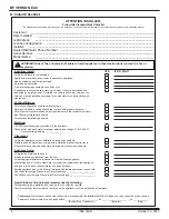
Page 3: ...or chimney connector glows you are over firing Any such action that may cause a fire hazard WARNING Fire Risk Hearth Home Technologies disclaims any responsibility for and the warranty will be voided...

Page 4: ...installation Location of the appliance and chimney will affect performance Consideration must be given to Safety convenience traffic flow Placement of the chimney and chimney connector and to minimiz...

Page 5: ...lasses Framing Square Electric Drill Bits 1 4 Level May also need Vent Support Straps Venting Paint Tools and building supplies normally required for installation unless installing into an existing ma...

Page 6: ...checklist for your file That this checklist remain visible at all times on the appliance until the installation is complete Electrical 120 VAC unswitched power provided to the appliance Check outlet w...

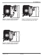
Page 7: ...1 8 in 155mm 6 1 8 in 155mm 14 in 357mm q q 5 13 16 in 147mm 2 9 16 in 65mm 3 13 16 in 97mm 14 1 16 in 357mm Figure 7 2 Top View with Top Vent Adapter TPVNT 3 and Offset Adapter 811 0720 Figure 7 4 To...

Page 8: ...e View Figure 8 4 Side View with Top Vent Adapter TPVNT 3 and Offset Adapter 811 0720 Figure 8 2 Front View 28 1 8 in 714mm 32 in 813mm 11 3 4 in 297mm 18 1 2 in 469mm 28 7 16 in 722mm Figure 8 1 Top...

Page 9: ...PVNT 3 and Offset Adapter 812 3570 Figure 9 2 Side View with Top Vent Adapter TPVNT 6 and Offset Adapter 812 3570 Figure 9 3 Side View with Top Vent Adapter TPVNT 6 and Offset Adapter 811 0720 25 1 2...

Page 10: ...ck Wall to Appliance 8 203 Installations with TPVNT 3 Top Vent Adapter with Heat Shield and Clean out TPVNT 6 Top Vent Adapter with Clean out 811 0720 3 to 4 Offset Adapter 812 3570 3 to 6 Offset Adap...

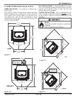
Page 11: ...area to the wall thimble 152mm 152mm FUEL DOOR OPENING 514mm minimum 44 1 8 in 22 5 8 in 24 1 4 in 39 3 4 in USA 6 in from the fuel door opening 1121mm 575mm 616mm 1010mm 152mm front door opening CANA...

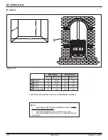
Page 12: ...llustrations diagrams are not drawn to scale Actual installation may vary due to individual design preference D Alcove Figure 12 1 All minimums listed are to a combustible surface Minimum Maximum Inch...

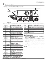
Page 13: ...paved driveway located on public property M 12 in Under an open veranda porch deck or balcony N See Note below Electric service above below or to the side location must not obstruct or interfere with...

Page 14: ...demands of the pellet appliance but consideration must be given to the total house demand House demand may consume the air needed for the appli ance It may be necessary to add additional ventilation...

Page 15: ...ly or horizontally 2 Mobile Home Approved for all Listed pellet vent If using the 3 inch 76mm vertical Top Vent Adapter Kit or the 3 to 6 inch 76 152mm Top Vent Offset Adapter use Listed double wall f...

Page 16: ...you may use 3 or 4 inch 76 to 102mm diameter type L or PL vent G Pipe Selection Chart The chart will help you in determining proper venting size according to the equivalent feet of pipe calculated pr...

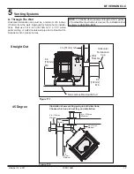
Page 17: ...mm Minimum 2 in 51mm Minimum 6 in 152mm Minimum 6 in 152mm Minimum 45 Degree 5 Venting Systems A Through The Wall Horizontal termination cap must be a minimum of 6 inches 152mm from the wall Approved...

Page 18: ...stop Non combustible Hearth Pad 12 in 305 mm Minimum Rain Cap Flashing 3 in 76mm Min 6 in 152mm Min 3 to 3 in 76 to 76mm Top Vent Kit Clean out Cover Figure 18 3 All three installations are approved f...

Page 19: ...5mm clearance with firestop Figure 19 1 Figure 19 2 Concrete Cap Non combustible Hearth Pad 6 in 152mm Min Airtight clean out door Sheathing 1 in 25mm clearnance Flashing Fireclay Flue Liner with airs...

Page 20: ...T INCLUDED Tools Needed Phillips head screw driver wire cutters hole saw or jig saw 1 Measure distance from floor to air vent opening in appli ance and mark location on wall Use saw to cut opening in...

Page 21: ...4 Install the 5 mounting screws 3 on the left and 2 on the right 5 Drill 2 holes with 26 drill bit through the rear exhaust outlet using the 2 holes already in the short horizontal pipe in the top ven...

Page 22: ...e appliance warranty Figure 22 1 Log fits over screws Left Log Log has indentations on the bottom to fit over the screw heads Log rests in front of screws Right Log Figure 22 3 Figure 22 4 E Optional...

Page 23: ...terminal block located on the back lower left corner of the appliance directly above the power cord inlet The center 2 screws are for the thermostat wires Figure 23 2 Programming Thermostat The thermo...

Page 24: ...e next time period Leave Repeat steps 2 and 3 for each weekday time period 5 Press NEXT to set weekend time periods Sat Sun then press DONE to save exit NOTE You can press CANCEL PERIOD to eliminate u...

Page 25: ...w for variations in elevation venting and installation configurations and fuel types hard wood soft wood Rotating this dial will adjust the air fuel ratio to the appliance Clockwise adjustments increa...

Page 26: ...art Number OAK 3 NEVER INSTALL IN A SLEEPING ROOM WARNING Spark Arrestor Cap Roof Flashing Storm Collar Joist Shield Firestop Approved Class L or PL Pellet Vent Figure 26 1 CAUTION Never draw outside...

Page 27: ...ssembly 18 120 VAC 300 Watt Wood Pellet Fuel Only SRV7000 647 Y Pkg of 10 SRV7000 647 10 Y Wing Thumb Screw 8 32 X 1 2 Pkg of 24 7000 223 24 Y Wire Clip Pkg of 10 7000 400 10 Y ACCESSORIES Collar Offs...

Page 28: ...e purchased installed _________________________________________________________________________ Serial Number ____________________________________ Location on appliance ___________________________ Dea...

Reviews: