


October 28, 2014
7080-131D
17
MT VERNON E2
6
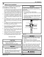
Appliance Set-Up
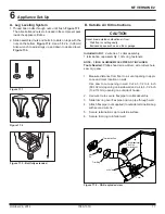
Figure 17.3 - Bolt fully extended
Figure 17.2
Figure 17.1
A. Leg Leveling System
1. Thread Allen bolts through nuts until fl ush.
Figure 17.1.
The Allen bolts and nuts are included in the component pack
inside the appliance fi rebox.
2. Slide assembled nuts and bolts into slots on legs with the
nuts on the bottom.
Figure 17.2
. Use a 5/32 in. (3.96mm)
Allen wrench to adjust legs up and down to desired level.
Figure 17.3.
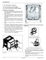
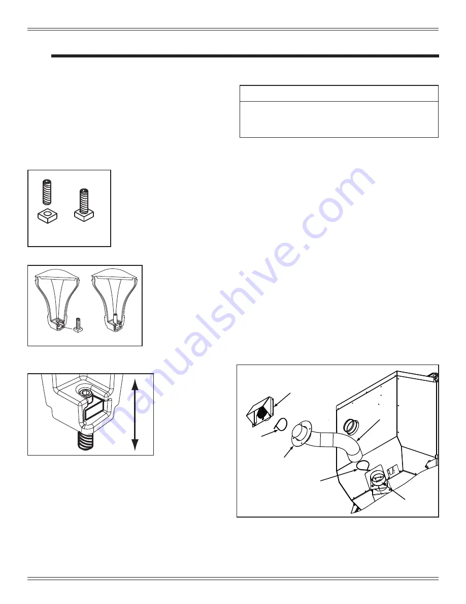
B. Outside Air Kit Instructions
Included in Kit
: 2 wire ties, 1 collar assembly,
1 termination cap assembly, 1 trim ring, fasteners.
NOTE:
3 INCH ALUMINUM
FLEX PIPE NOT INCLUDED.
Tools Needed:
Phillips head screw driver; wire cutters hole
saw or jig saw.
1. Measure distance from fl oor to air vent opening in appli-
ance and mark location on wall.
Use saw to cut opening in wall. Cut a 3-1/2 to 4 inch
(89-102mm) opening on inside wall and a 4 to 4-1/2 inch
(102-114mm) opening on outside of house.
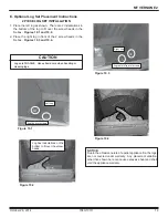
2. Use wire tie to secure fl ex pipe to collar assembly.
3. Slide trim ring over fl ex pipe and run pipe through wall.
4. Attach
fl ex pipe (not supplied) to outside termination cap
with second wire tie.
5. Secure termination cap to outside surface.
6. Secure trim ring to interior wall.
CAUTION
Never draw outside combustion air from:
• Wall,
fl oor or ceiling cavity
• Enclosed space such as an attic or garage
Figure 17.4 - OAK exploded view
Termination Cap
Wire
Tie
Trim Ring
Wire Tie
Collar
3 inch Aluminum
Flex Pipe
(not included)


