October 28, 2014
7080-131D
21
MT VERNON E2
7
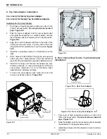
Mobile Home Installation
You must use a Quadra-Fire Outside Air Kit
for installation in a mobile home.
1.
An outside air inlet must be provided for the combustion
air and must remain clear of leaves, debris, ice and/or
snow. It must be unrestricted while the appliance is in
use to prevent room air starvation which causes smoke
spillage. Smoke spillage can also set off smoke alarms.
2.
The combustion air duct system must be made of metal.
It must permit zero clearance to combustible construc-
tion and prevent material from dropping into the inlet or
into the area beneath the dwelling and contain a rodent
screen.
3. The appliance must be secured to the mobile home
structure by bolting it to the fl oor (using lag bolts). Use
the same holes that secured the appliance to the shipping
pallet.
4.
The appliance must be grounded with #8 solid copper
grounding wire or equivalent, terminated at each end
with an NEC approved grounding device.
5.
Refer to Clearances to Combustibles and fl oor protection
requirements on
page 8
for listings to combustibles and
appropriate chimney systems.
6.
Use silicone to create an effective vapor barrier at the
location where the chimney or other component pene-
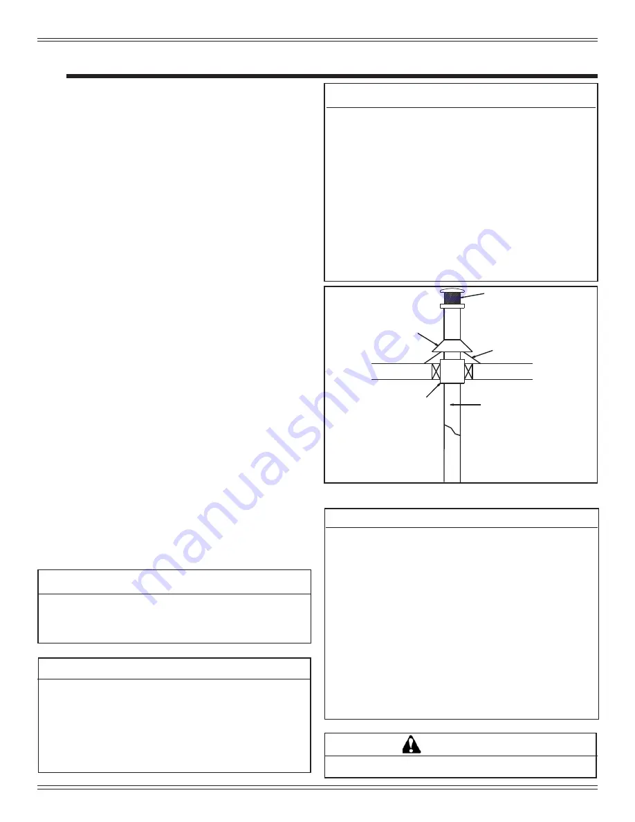
trates to the exterior of the structure.
7. Follow the chimney manufacturer’s instructions when
installing the vent system for use in a mobile home.
8.
Installation shall be in accordance with the Manufacturers
Home & Safety Standard (HUD) CFR 3280, Part 24.
Part Number: OAK-3
NEVER INSTALL IN A SLEEPING ROOM.
WARNING
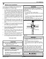
Spark Arrestor Cap
Roof Flashing
Storm Collar
Joist Shield/Firestop
Approved Class L
or PL Pellet Vent
Figure 21.1
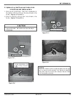
CAUTION
Never draw outside combustion air from:
• Wall,
fl oor or ceiling cavity
• Enclosed space such as an attic or garage
CAUTION
THE STRUCTURAL INTEGRITY OF THE MOBILE
HOME FLOOR, WALL AND CEILING/ROOF MUST BE
MAINTAINED
Do NOT cut through:
• Floor joist, wall, studs or ceiling trusses.
• Any supporting material that would affect the structural
integrity.
This unit is to be connected to a factory-built chimney
conforming to CAN/ULC-S629, Standard for 650°C
Factory-Built Chimneys.
For removal of the chimney for mobile home transpor-
tation, contact the proper transportation offi cials.
WARNING
Products of combustion generate carbon monoxide
and different fuels generate different levels. Carbon
monoxide
•
Only use approved fuels in this appliance.
•
Always keep door shut during operation. Operating
this unit with doors open can allow CO to leak into the
home.
CO can kill you before you are aware it is in your home.
At lower levels of exposure, CO causes mild effects
that are often mistaken for the fl u. These symptoms
include headaches, dizziness, disorientation, nausea
and fatigue. The effects of CO exposure can vary greatly
from person to person depending on age, overall health
and the concentration and length of exposure.
WARNING
It is critical to have a working smoke detector
installed in the home of unit operation.
•
Smoke alarms that are properly installed and maintained
play a vital role in reducing fi re deaths and injuries.
Having a working smoke alarm reduces the chance of
fi re related injuries..