background image

 6 


7080-131D 


           October 28, 2014

MT VERNON E2

ATTENTION INSTALLER:

Follow this Standard Work Checklist

This standard work checklist is to be used by the installer in conjunction with, not instead of, the instructions contained in this installation manual.


Customer: 


 Date Installed: 

 Lot/Address:

 Location of Fireplace:
 Installer

 Dealer/ Distributor Phone #:
 Serial #: 

 Model (circle one):    

MTV-E2-

MBK

             MTV-E2-

CSB 

  MTV-E2-

PFT


  MTV-E2-

PDB


        MTV-E2-

PBK         

MTV-E2-

PMH

WARNING! Risk of Fire or Explosion!  Failure to install fi replace according to these instructions can lead to a fi re or explosion.

Hearth & Home Technologies recommends the following:

• Photographing the installation and copying this checklist for your fi le.

• That this checklist remain visible at all times on the fi replace until the installation is complete.

Comments: 

Further description of the issues, who is responsible (Installer/Builder/Other Trades, etc.) and corrective action needed:

Comments communicated to party responsible                                                         by                                             on                    


(Builder/Gen. Contractor)                           (Installer)                        (Date)

Part # 4017-254 • Rev B • 01/29/13

E. Install Checklist
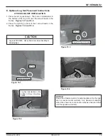
Appliance Install                                                                                              

Required non-combustible fl oor protection (Pg. 9)
Verifi ed clearance to combustible (Pg. 8)
Unit is leveled and secured (Pg. 18) 

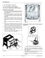
Venting/Chimney Section 4 (Pg. 12)

Venting confi guration complies with diagrams
Venting installed, sealed and secured in place with proper clearance
Exterior wall/roof fl ashing installed and sealed
Terminations installed and sealed
OAK installed and sealed (if needed) (Pg. 16 & 17)
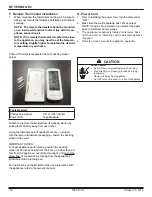
Electrical

120VAC unswitched power provided to the appliance (Pg. 21)

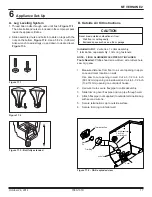
Appliance Setup Section 5 (Pg. 17)

All packaging and protective materials removed
Accessories installed properly
Started appliance and verifi ed that all motors and blowers operate as the should
Manual bag and all of its contents are removed from inside/under the fi replace
     and given to the party responsible for use and operation.

YES       IF NO, WHY?

Summary of Contents for MTV-E2-CSB

Page 1: ...other flam mable vapors and liquids in the vicinity of this or any other appliance Do not overfire If heater or chimney con nector glows you are overfiring Overfiring will void your warranty Comply wi...

Page 2: ...B Remote Thermostat Location 5 C Tools And Supplies Needed 5 D Inspect Appliance and Components 5 E Install Checklist 6 3 Dimensions and Clearances 7 A Appliance Dimensions 7 B Clearances to Combusti...

Page 3: ...aterials reported as passing ASTM E 136 Standard Test Method for Behavior of Metals in a Vertical Tube Furnace of 750 C G Combustible Materials Material made of or surfaced with any of the following m...

Page 4: ...installation Location of the appliance and chimney will affect performance Consideration must be given to Safety convenience traffic flow Placement of the chimney and chimney connector and to minimize...

Page 5: ...mostat s location will have some affect on the appliance s operation When located close to the appliance it may require a slightly higher temperature setting to keep the rest of the house comfortable...

Page 6: ...responsible Installer Builder Other Trades etc and corrective action needed Comments communicated to party responsible by on Builder Gen Contractor Installer Date Part 4017 254 Rev B 01 29 13 E Instal...

Page 7: ...ure 7 5 Side View Figure 7 2 Side View with Top Vent Adapter and 3 to 6 in 76 152mm Offset Adapter 31 1 16 788 29 3 16 741 q 5 13 16 147 2 9 16 65 3 13 16 97 14 1 16 357 28 1 8 714 32 5 16 821 28 7 16...

Page 8: ...e when installed with horizontal venting or under the Top Vent Adapter with vertical installation CANADA INSTALLATIONS A non combustible floor pro tection extending beneath the flue pipe is required w...

Page 9: ...lustrations diagrams are not drawn to scale Actual installation may vary due to individual design preference D Alcove Figure 9 1 All minimums listed are to a combustible surface Minimum Maximum Inches...

Page 10: ...nd protruding parts of the structure P 12 in Clearance above roof line for vertical terminations All minimum clearances are listed with an Outside Air Kit OAK installed unless otherwise noted in table...

Page 11: ...he exhaust vent outlet and located lower on the wall than the exhaust vent outlet The outside air supply kit can supply most of the demands of the pellet appliance but consideration must be given to t...

Page 12: ...E Hearth Home Technologies assumes no responsibility for the improper performance of the chimney system caused by Inadequate draft due to environmental conditions Downdrafts Tight sealing construction...

Page 13: ...you may use 3 or 4 inch 76 to 102mm diameter type L or PL vent G Pipe Selection Chart The chart will help you in determining proper venting size according to the equivalent feet of pipe calculated pre...

Page 14: ...m Minimum 2 in 51mm Minimum 6 in 152mm Minimum 6 in 152mm Minimum 45 Degree 5 Venting Systems A Through The Wall Horizontal termination cap must be a minimum of 6 inches 152mm from the wall Approved f...

Page 15: ...Minimum Rain Cap Flashing 3 in 76mm Min 6 in 152mm Min 3 to 3 in 76 to 76mm Top Vent Kit Clean out Cover Figure 15 3 We recommend a minimum of 60 inches 1524mm vertical however above the eave is prefe...

Page 16: ...mm clearance with firestop Figure 16 1 Figure 16 2 Concrete Cap Non combustible Hearth Pad 6 in 152mm Min Airtight clean out door Sheathing 1 in 25mm clearnance Flashing Fireclay Flue Liner with airsp...

Page 17: ...INCLUDED Tools Needed Phillips head screw driver wire cutters hole saw or jig saw 1 Measure distance from floor to air vent opening in appli ance and mark location on wall Use saw to cut opening in w...

Page 18: ...nstall the 5 mounting screws 3 on the left and 2 on the right 5 Drill 2 holes with 26 drill bit through the rear exhaust outlet using the 2 holes already in the short horizontal pipe in the top vent a...

Page 19: ...appliance warranty Figure 19 1 Log fits over screws Left Log Log has indentations on the bottom to fit over the screw heads Log rests in front of screws Right Log Figure 19 3 Figure 19 4 E Optional L...

Page 20: ...ll bit Tape Measure Detach the remote thermostat from its docking station by pulling them directly away from each other Using the fasteners and if needed anchors included with the remote transmitter p...

Page 21: ...t 24 Part Number OAK 3 NEVER INSTALL IN A SLEEPING ROOM WARNING Spark Arrestor Cap Roof Flashing Storm Collar Joist Shield Firestop Approved Class L or PL Pellet Vent Figure 21 1 CAUTION Never draw ou...

Page 22: ...3 Y Damper 4 Inch Tall Vertical Installs Only PEL DAMP4 Firescreen No Longer Available SCR 7005 Log Set Sold as Set only 2 Pc LOGS 60 AE B Outside Air Kit OAK 3 Top Vent Adapter TPVNT 3 Warming Shelve...

Page 23: ...October 28 2014 7080 131D 23 MT VERNON E2...

Page 24: ...lville WA 99114 Division of HNI INDUSTRIES Please contact your Quadra Fire dealer with any questions or concerns For the number of your nearest Quadra Fire dealer log onto www quadrafire com This prod...

Reviews: