
8
7080-131D
October 28, 2014
MT VERNON E2
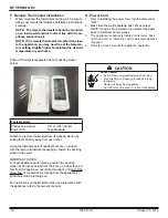
Straight Back Against Wall
Inches
Millimeters
A
Back Wall to Appliance
2
51
B
Side Wall to Appliance
6
152
Corner Installation
Inches
Millimeters
C
Walls to Appliance
2
51
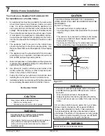
Vertical Installation
Inches
Millimeters
D
Back Wall to Flue Pipe
3
76
E
Side Wall to Appliance
6
152
F
Back Wall to Appliance
8
203
Installations with:
3 to 3 inch Top Vent Adapter and
3 to 6 inch Offset Adapter Kit
Corner Installation
Inches
Millimeters
G
Side Wall to Flue Pipe
3
76
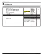
Alcove Installation
Inches
Millimeters
Minimum Alcove Height
43
1092
Minimum Alcove Side Wall
6
152
Minimum Alcove Width
40
1016
Maximum Alcove Depth
36
914
D
E
F
A
B
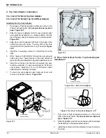
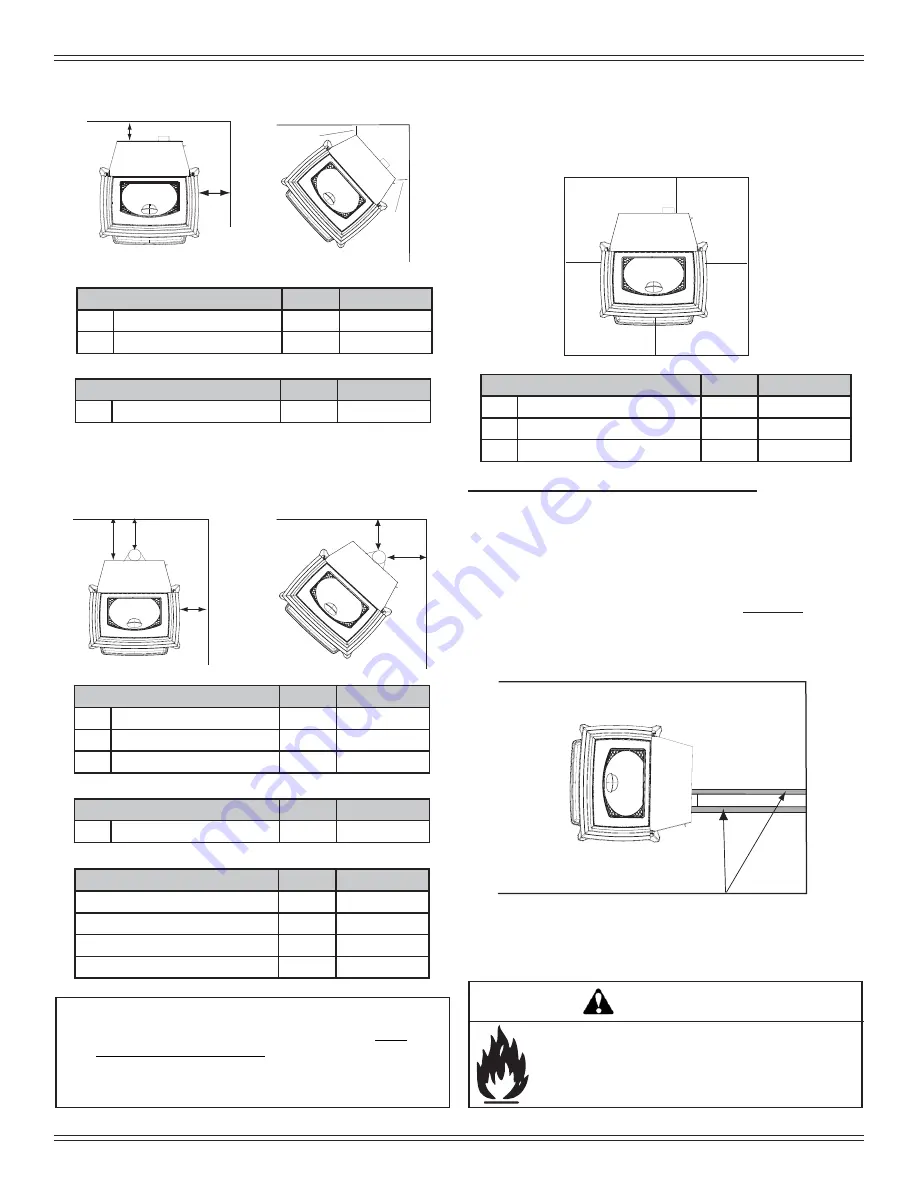
*L Exception for Horizontal Installations:
USA INSTALLATIONS
: A non-combustible fl oor protec-
tion is recommended extending beneath the fl ue pipe when
installed with horizontal venting or under the Top Vent
Adapter with vertical installation.
CANADA INSTALLATIONS
: A non-combustible fl oor pro-
tection extending beneath the fl ue pipe is
required
with hor-
izontal venting or under the Top Vent Adapter with vertical
installation.
Must extend 2 inches (51mm) beyond each
side of pipe (shaded area)
NOTE:
•
Illustrations
refl ect typical installations and are FOR
DESIGN PURPOSES ONLY.
•
I
llustrations/diagrams are not drawn to scale.
•
Actual installation may vary due to individual design
preference.
C
C
G
G
L*
K
K
M
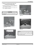
Use a non-combustible fl oor protector, extending beneath
appliance and to the front, sides and rear as indicated. Mea-
sure front distance “M” from the surface of the glass door.
Hearth Pad Requirements
Inches
Millimeters
K
Sides
2
200
L*
Back
2
200
M
Front
6
450
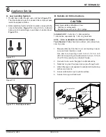
B. Clearances to Combustibles (US & Canada)
C. Hearth Pad Requirements (US & Canada)
Fire Risk.
Comply with all minimum clearances to combustibles
as specifi ed.
Failure to comply may cause house fi re.
WARNING