background image

Page  42

7034-106E

September 1, 2008

R

Mt. Vernon Pellet Stove (AE)

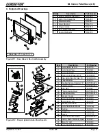
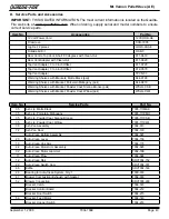
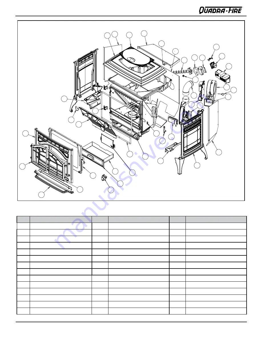
Figure 42.1

Item

Description

Item

Description

Item

Description

35

Ash Lip

49

Exhaust Transition

63

Shroud, Left

36

Door, Cast, Right

50

Gasket, Blower, Convection

64

Top, Cast

37

Door Assembly

51

Detent Pin 3/16

65

Side Mount, Left

38

Ash Pan Assembly

52

Blower, Convection

66

Hinge, Male, Door

39

Gasket, Ash Door

53

Power Supply

67

Latch, Baffle

40

Gasket, (Rope) Door

54

Feed Motor

68

Baffle

41

Switch, Magnetic 

55

Switch, Optical Assembly

69

Front, Cast

42

Bracket, Latch

56

Bracket, Feed Motor

70

Door, Cast, Left

43

Vacuum Switch

57

Sensor, Overheat (Snap Disc)

71

Clip Receiver

44

Side Mount, Right

58

Gasket, Feed Motor

72

Ash Pan Door

45

Side, Cast. Left & Right

59

Feed Spring Assembly

73

Intake Shield

46

Shroud, Right

60

Shroud, Rear

47

Blower, Combustion (Exhaust)

61

Hopper Top

48

Control Board

62

Hopper Lid

Summary of Contents for MTVERNON-AE-MBK

Page 1: ...odily injury or even death Do not store or use gasoline or other am mable vapors and liquids in the vicinity of this or any other appliance Do not over re If any external part starts to glow you are o...

Page 2: ...J K I 2 in 51mm J 2 in 51mm K 6 in 152mm G G D E F C C A B 2007 2008 2009 JAN FEB MAR APR MAY JUN JULY AUG SEPT OCT NOV DEC Mt Vernon Pellet Stove AE Report Rapport 061 S 68 6 OMNI Test Laboratories I...

Page 3: ...G Alternate Masonry 16 Section 6 Mobile Home Installation 17 Section 7 Appliance Set Up A Leg Leveling System 18 B Outside Air Kit 18 C Top Vent Adapter 19 D Rear Vent Adapter 19 E Log Set Placement 2...

Page 4: ...d ULC ORD C 1482 D Electrical Rating 115 VAC 60 Hz Start 5 Amps Run 1 25 Amps BTU output will vary depending on the type of fuel you use in your stove Consult your Quadra Fire dealer for best results...

Page 5: ...on of the vent termination T O If burning shelled field corn you must use ap proved venting specifically designed for corn to prevent corro sion or degradation Follow the instructions from the venting...

Page 6: ...he intake facing prevailing winds during the heating season Ensure adequate outdoor air for all combustion appliances and exhaust equipment Ensure furnace and air conditioning return vents are not loc...

Page 7: ...easure Plumb Line Level Framing Material Hi temp Caulking Material Gloves Safety Glasses Framing Square Electric Drill Bits 1 4 1 4 Self Tapping Screws May also need Vent Support Straps Venting Paint...

Page 8: ...6 152mm Adapter Figure 8 5 Side View Figure 8 2 Side View with Top Vent Adapter and 3 to 6 in 76 152mm Offset Adapter 29 3 6 in 741mm 31 1 6 in 788mm C L 5 13 16 in 147mm 3 13 16 in 97mm 14 1 16 in 35...

Page 9: ...protec tion is recommended extending beneath the ue pipe when installed with horizontal venting or under the Top Vent Adapter with vertical installation CANADA INSTALLATIONS A non combustible oor prot...

Page 10: ...regulator I 36 in USA 72 in Canada Clearance to service regulator vent outlet J 12 in 48 in no OAK Clearance to non mechanical air supply inlet to the building or the combustions air inlet to any oth...

Page 11: ...east 3 screws through each joint NOTE All pipe must be welded seam pipe whenever possible Seal pipe joints with high temperature silicone 500 F 260 C minimum rated only NOTE If burning shelled field c...

Page 12: ...gases under positive pressure as one foot of horizontal pipe and a foot of horizontal pipe is twice as restrictive as a foot of vertical pipe D Pipe Selection Chart Figure 12 1 Fire Risk Do NOT pack...

Page 13: ...SES ONLY Illustrations diagrams are not drawn to scale Actual installation may vary due to individual design preference A Alcove Figure 13 1 All minimums listed are to a combustible surface Minimum Ma...

Page 14: ...le home installa tions Must use 3 or 4 inch 76 102mm L or PL Listed pellet venting or Listed double wall pipe and a Quadra Fire Outside Air Kit in mobile homes NOTE In Canada where passage through a w...

Page 15: ...duced clearances are allowed C Vertical into Existing Class A Chimney D Through The Wall Vertical Exterior Firestop Flashing Rain Cap 6 in 152mm Min Non combustible Hearth Pad 3 in 76mm Min Clean out...

Page 16: ...h Pad Airtight clean out door Sheathing Flashing 1 in 25mm clearance 1 in 25mm clearance with firestop 6 in 152mm minimum Fireclay Flue Liner with airspace Concrete Cap 2 in 51mm minimum to combustibl...

Page 17: ...NEC approved grounding device 5 Refer to Clearances to Combustibles and oor protec tion requirements on page 9 for listings to combustibles and appropriate chimney systems 6 Use silicone to create an...

Page 18: ...ing in wall Cut a 3 1 2 to 4 inch 89 102mm opening on inside wall and a 4 to 4 1 2 inch 102 114mm opening on outside of house 2 Use wire tie to secure ex pipe to collar assembly 3 Slide trim ring over...

Page 19: ...crews Figure 19 2 6 Install the vent pipe into the top vent adapter be sure to silicone all joints To use an existing 6 inch 152mm vent system install the 3 to 6 in 76 152mm offset adapter before inst...

Page 20: ...an shown here can cause excessive heat and shall void the appliance warranty Figure 20 1 Log fits over screws Left Log Log has indentations on the bottom to fit over the screw heads Log rests in front...

Page 21: ...of the appliance directly above the power cord inlet The center 3 screws are for the wall control thermostat wires and the 2 outer screws are mounting screw and should not have wires attached to them...

Page 22: ...em We recommend that you buy fuel in multi ton lots whenever possible However we do recommend trying various brands before purchasing multi ton lots to ensure your satisfaction Tested and approved for...

Page 23: ...creen Automatic Manual Off Figure 23 1 C Before Your First Fire 1 First make sure your appliance has been properly installed and that all safety requirements have been met Pay particular attention to...

Page 24: ...Ignition Cycles The Advanced Energy engine is controlled by the digital wall control The digital display on the wall control will tell you what your appliance is doing in the upper left corner above t...

Page 25: ...eeding fuel and allow the re to dimin ish The convection blower will continue to run until the appliance cools to appropriate temperature and will go into the auto clean cycle 5 Auto Clean The repot a...

Page 26: ...e hopper lid and glass door are both closed 1 At the starting screen press MENU Function Buttons ttons Up Down R A Set at P HEAT OUTPUT MENU Room Temp Wall Control for Reference 6 Press DONE twice or...

Page 27: ...OUTPUT LEVEL to MEDIUM HIGH SETTING HEAT OUTPUT 1 Press and hold UP or DOWN but ton to set desired temperature F 2 Press HOLD TEMP SETTING COMFORT LEVEL R A Set at P HEAT OUTPUT MENU NOTE Set tempera...

Page 28: ...low the more frequent clean ing of the glass is required 4 Fire has tall ames with black tails and is lazy 4 The ame height adjustment needs to be reduced or the repot needs cleaning Heat exchanger or...

Page 29: ...m hose COMB BLOWER JAMMED Combustion blower is blocked jammed Remove blockage Replace blower if necessary Must uplug the appliance to clear the error AUGER JAMMED Auger jammed feed motor bad Pull the...

Page 30: ...ncy Daily Weekly Every 2 Weeks Monthly Yearly Ash Pan Burning Pellets Every 5 bags of fuel OR X Ash Pan Burning Alternate Fuels Every 1 bag of fuel OR X Ash Removal from Firebox More frequently depend...

Page 31: ...frequently depending on fuel type By Homeowner a The appliance must be in complete shutdown completely cool and the exhaust blower off b Inspect the auto clean springs for any degradation or deformati...

Page 32: ...e shutdown completely cool and the exhaust blower off b It is necessary to remove the baf e to gain access to the heat exchanger Follow instructions for baf e removal on page 35 c Vacuum the ash from...

Page 33: ...ear of the appliance Figure 33 1 2 Use an 11 32 nut driver to loosen all six nuts but do not remove Rotate the blower and remove from the housing Figure 33 2 3 Set the blower on the top of the housing...

Page 34: ...ct your local dealer 13 Soot and Fly Ash Formation Need for Removal in Exhaust Venting System Frequency Yearly or more frequently depending on fuel type or ash build up By Quali ed Service Technician...

Page 35: ...own The bottom of the latch will fall forward off of the post Lift the baf e up and then out toward you Figure 35 2 e To replace the baf e place the 2 locating ears behind the bottom edge and tilt the...

Page 36: ...ere will be room to remove the blower Figure 36 1 5 Reach behind the blower and release the latch by push ing the top of the latch towards the blower Figure 36 2 6 Rock the top of the blower slightly...

Page 37: ...lined on page 30 Section 10 A 2 Remove the right side panel by removing the 4 screws using a Phillips head screw driver Figure 37 1 3 It is not necessary or recommended to remove the housing to replac...

Page 38: ...quality surge protector is hightly recommended to protect the electronics When describing the location of a component it is always AS YOU FACE THE FRONT OF THE APPLIANCE 6 Convection Blower The convec...

Page 39: ...tch is located on the right side of the appliance under the feed motor behind right side panel and connects to the drop tube with a hose This switch turns the feed system on when vacuum is present in...

Page 40: ...sh Pan Thermocouple and Thermocouple Cover Heat Exchanger Front Back Figure 40 1 RIGHT SIDE Combustion Blower Vacuum Switch Feed Motor Overheat Sensor Wing Nut Securing Overheat Sensor in place Power...

Page 41: ...g Element Igniter 18 SRV7000 226 17 Thermocouple SRV7000 334 18 Clip Half 7000 321 19 Thermocouple Cover SRV7034 186 20 Firepot Assembly SRV7034 010 21 Gasket Firepot 7034 190 22 Auto Clean Motor Arm...

Page 42: ...tion 66 Hinge Male Door 39 Gasket Ash Door 53 Power Supply 67 Latch Baf e 40 Gasket Rope Door 54 Feed Motor 68 Baf e 41 Switch Magnetic 55 Switch Optical Assembly 69 Front Cast 42 Bracket Latch 56 Bra...

Page 43: ...4 9810 Warming Shelves with Bracket Powder Coat Sienna Bronze pair WSLG CSB Warming Shelves with Bracket Powder Coat Willow pair WSLG CWL Item No Service Parts Part No 35 Ash Lip Matte Black 7005 111M...

Page 44: ...or Assembly 7034 006 6 Door Frame Assembly 7034 026 7 Door Air De ector 7034 185 2 Door Latch Assembly 7034 039 70 Door Left Matte Black 7005 110MBK 70 Door Left Porcelain Mahogany 7005 110PMH 70 Door...

Page 45: ...7034 138 Hinge Pin Hopper Lid Qty 1 7034 159 Hinge Retainer Hopper Lid 7034 163 62 Hopper Lid Matte Black 7034 157MBK 62 Hopper Lid Porcelain Mahogany 7034 157PMH 62 Hopper Lid Powder Coat Sienna Bro...
Page 46: ...etic 7000 375 30 Switch Micro Normally Open 7000 327 55 Switch Optical Assembly 7034 038 17 Thermocouple Firepot SRV7000 334 19 Thermocouple Cover SRV7034 186 Thermocouple Ring Mount SRV7000 381 Therm...

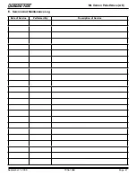
Page 47: ...R September 1 2008 7034 106E Page 47 Mt Vernon Pellet Stove AE Date of Service Performed By Description of Service E Service And Maintenance Log...

Page 48: ...Page 48 7034 106E September 1 2008 R Mt Vernon Pellet Stove AE Date of Service Performed By Description of Service E Service And Maintenance Log Cont d...

Page 49: ...R September 1 2008 7034 106E Page 49 Mt Vernon Pellet Stove AE F Homeowner s Notes...

Page 50: ...ee Conditions Exclusions and limitations 9 01 08 CONDITIONS EXCLUSIONS LIMITATION OF LIABILITY This warranty applies to the original owner and is transferable up to two years from date of purchase to...

Page 51: ...chlorine uorine or other damaging chemicals the appliance is subject to prolonged periods of dampness or condensation or there is any damage to the appliance or other components due to water or weathe...

Page 52: ...45502 6170481 6237588 6296474 6374822 6413079 6439226 6484712 6543698 6550687 6601579 6672860 6688302B2 6715724B2 6729551 6736133 6748940 6748942 6769426 6774802 6796302 6840261 6848441 6863064 686620...

Reviews: