background image

September 24, 2015

7014-188L

Page  19

1200-I  Pellet Insert

6

Mobile Home

1. 

An outside air inlet must be provided for the combustion 
air and must remain clear of leaves, debris, ice and/or 
snow.  It must be unrestricted while the appliance is 
in use to prevent room air starvation which causes 
smoke spillage.  Smoke spillage can also set off smoke 
alarms.  

2. 

The combustion air duct system must be made of metal.  
It must permit zero clearance to combustible construc-
tion and prevent material from dropping into the inlet or 
into the area beneath the dwelling and contain a rodent 
screen.

3. 

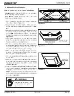
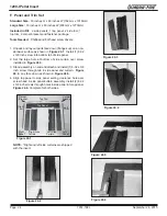
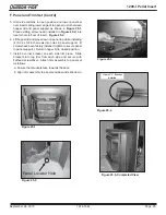
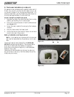
The appliance must be secured to the mobile home 
structure by bolting it to the fl oor (using lag bolts) in two 
places.  Use the same holes that secured the appliance 
to the shipping pallet.

4. 

The appliance must be grounded with #8 solid copper 
grounding wire or equivalent, terminated at each end 
with an NEC approved grounding device.

5.  Refer to Clearances to Combustibles and fl oor  pro-

tection requirements on 

pages 9


& 10

 for listings to 

combustibles and appropriate chimney systems.

6.  Use silicone to create an effective vapor barrier at 

the location where the chimney or other component 
penetrates to the exterior of the structure.

7. 

Follow the chimney manufacturer’s instructions when 
installing the vent system for use in a mobile home.

8. 

Installation shall be in accordance with the Manufactur-
ers Home & Safety Standard (HUD) CFR 3280, Part 
24.

Installation must comply with Manufactured Home and 
Safety Standard (HUD), CFR 3280, Part 24.

WARNING

You must use a Quadra-Fire Outside Air Kit 
for installation in a mobile home.

A. Mobile Home Installation

Spark Arrestor Cap

Roof Flashing

Storm Collar

Joist Shield/Firestop

Approved Class “L” 
or “PL” Pellet Vent

Figure 19.1

CAUTION

Never draw outside combustion air from:
• Wall, 

fl oor or ceiling cavity

•  Enclosed space such as an attic or garage

CAUTION

THE STRUCTURAL INTEGRITY OF THE MOBILE HOME 
FLOOR, WALL AND CEILING/ROOF MUST BE MAIN-
TAINED

Do NOT cut through:
•  Floor joist, wall, studs or ceiling trusses.
•  Any supporting material that would affect the structural 

integrity.

NEVER INSTALL IN A SLEEPING ROOM.

Consumes oxygen in the room.

WARNING

Asphyxiation Risk.

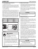
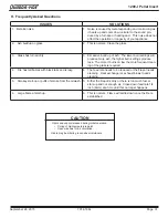
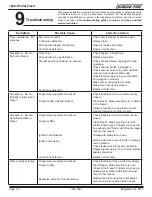
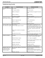
Summary of Contents for PELLET INSERT CB1200MI-MBK

Page 1: ...ilding codes prior to installation Installation MUST comply with local regional state and national codes and regulations Consult local building fire officials or authorities having jurisdic tion about restrictions installation inspection and permits CAUTION Tested and approved for wood pellets and shelled field corn fuel only Burning of any other type of fuel voids your warranty CAUTION O T L Test...

Page 2: ...3 2 DO NOT REMOVE THIS LABEL NE PAS ENLEVER L ÉTIQUETTE Manufactured by Fabriqué par 0 Omm Clearance To Exposed Section and Face Trim PRÉVENTION DES FEUX DE MAISON Installez et utilisez en accord avec les instructions d installation et d opération du fabricant Contactez le bureau de la construction ou le bureau des incendies au sujet des restrictions et des inspections d installation dans votre vo...

Page 3: ...ion 6 Mobile Home 19 Section 7 Appliance Set Up A Rear Shroud Installation 20 21 B Outside Air Kit 22 C Adjustable Hopper Option 22 D Grill Installation 22 E Adjustable Hearth Support 23 F Panel Trim 24 25 G Log Set Placement 26 H Thermostat Installation 26 Section 8 Operating Instructions A Fuel Size Material Storage 28 B General Operation Information 29 C Before Your First Fire 29 D Starting You...

Page 4: ...ency listing will be voided by the above actions DO NOT Install or operate damaged appliance Modify appliance Install other than as instructed by Hearth Home Technologies Operate the appliance without fully assembling all components Overfire Install any component not approved by Hearth Home Technologies Install parts or components not Listed or approved Improper installation adjustment alteration ...

Page 5: ...he loca tion of the vent termination CAUTION If burning shelled field corn you must use ap proved venting specifically designed for corn to prevent corro sion or degradation Follow the instructions from the venting manufacturer Since pellet exhaust can contain ash soot or sparks you must consider the location of Windows Air Intakes Air Conditioner Overhang soffits porch roofs adjacent walls Landsc...

Page 6: ...an appliance is drafting successfully all combustion by products are exiting the home through the chimney Considerations for successful draft include Preventing negative pressure Location of appliance and chimney NOTICE Hearth Home Technologies assumes no responsibility for the improper performance of the chimney system caused by Inadequate draft due to environmental conditions Downdrafts Tight se...

Page 7: ...y chimney is inspected by a profes sional and is clean or the factory built metal chimney is installed according to the manufac turer s instructions and clearances 9 The chimney meets the required minimum height 10 All labels have been removed from the glass door 11 Plated surfaces have been wiped clean if applicable 12 Thermostat or remote has been installed 13 A power outlet is available nearby ...

Page 8: ...Side View Panel A B Standard 30 inches 762mm 40 inches 1016mm Large 33 inches 838mm 50 inches 1270mm B A 30 in 762mm 22 in 559mm 19 1 2 in 495mm 11in 279mm 11 279mm 25 1 2 in 648mm 12 in 305mm 13 in 330mm 10 3 4 in 273mm Hopper Up Hopper Down C C L L 22 in 559mm 29 1 4 in 743mm 8 3 4 in 222mm 40 in 1016mm 13 in 330mm 12 in 305mm 28 1 2 in 724mm 10 3 4 in 273mm ...

Page 9: ...ANCE TO EXPOSED SECTION AND FACE TRIM Rear Shroud Kit is Required for Built In Installation A Top of Shroud Top Vent 3 0 76 Rear Vent 0 0 B Sides of Inside Shroud Top or Rear Vent 0 0 C Back of Inside Shroud Top Vent 2 5 64 Rear Vent 0 0 D Vent Pipe to Combustible Top or Rear Vent 3 0 76 E From Outside Edge of Panel Set to Combustibles 0 0 Inches Millimeters Fire Risk WARNING Failure to comply may...

Page 10: ...TE A Quadra Fire floor protector Part 811 0730 is available through your dealer to be used as a floor protec tor for the section under the insert body only Floor protec tion to front and sides of insert unit must be supplied in addition to this part F Floor Protection 1 Zero Clearance Installations It is necessary to install a floor protection of non combus tible material with a R value of 3 0 1 i...

Page 11: ... of a material s resistance to heat transfer R value is convenient when more than one materi al is used since you can add the R values together whereas you can not do this for k value The HIGHER the R fac tor means less heat is being conducted through the non combustible material to the combustible material beneath it The R value of a material must be equal or larger then the required R value to b...

Page 12: ...fireplace for reassembly if the insert is removed The permanent metal warning label provided must be attached to the back of the fireplace with screws or nails stating that the fireplace may have been altered to accommodate the insert and must be returned to original condition for use as a conventional fireplace Figure 12 1 250 2061 WARNING THIS FIREPLACE MAY HAVE BEEN ALTERED TO ACCOMMODATE AN IN...

Page 13: ...e approved chimney liner meeting type UL 103 HT requirements 2100 F per UL 1777 If the chimney is not listed as meeting HT requirements or if the factory built fireplace was tested prior to 1998 a full height listed chimney liner must be installed from the appliance flue collar to the chimney top The liner must be securely attached to the insert flue collar and the chimney top The air flow of the ...

Page 14: ...g fences and protruding parts of the structure P 12 in Clearance above roof line for vertical terminations All minimum clearances are listed with an Outside Air Kit OAK installed unless otherwise noted in table below 24 in Above grass top of plants wood or any other com bustible 12 in 36 in no OAK Clearance from any forced air intake of other appli ance 12 in Clearance horizontally from combustibl...

Page 15: ...same as minimum clearance to vinyl inside corners Clearance of a termination cap below electrical service shall be the same as minimum clearance to vinyl soffits Clearance of a termination cap above electrical service will be 12 inches 305mm minimum Location of the vent termination must not obstruct or interfere with access to the electrical service 1 Chimney Connector Use 3 or 4 inch 76 102mm dia...

Page 16: ...e flow of exhaust gases under positive pressure as 1 foot of horizontal pipe and a foot of horizontal pipe is twice as restrictive as a foot of vertical pipe E Pipe Selection Chart The table below can help you calculate the equivalent feet of pipe which is a method used to determine pellet vent size See Figure 16 1 D Equivalent Feet of Pipe 2 ft 2 ft 3 ft 2 ft Example of 3 Elbow Rear Vent Terminat...

Page 17: ...aw outside combustion air from Wall floor or ceiling cavity Enclosed space such as an attic or garage NOTE Illustrations reflect typical installations and are FOR DESIGN PURPOSES ONLY Illustrations diagrams are not drawn to scale Actual installation may vary due to individual design preference A Full Reline With Outside Air Horizontal Outside Air through Rear Wall Horizontal NOTE Use metal plate a...

Page 18: ...ne With Outside Air Vertical Figure 18 1 Outside Air Termination at Chimney Top Vertical 305mm min below 305mm min above NOTE Use metal plate around exhaust vent pipe and seal all edges with non flammable insula tion such as mineral wool or ceramic Do not use high temperature caulk ing materials to seal any edge to prevent furture serviceability NOTE In Canada this fireplace insert must be install...

Page 19: ...on pages 9 10 for listings to combustibles and appropriate chimney systems 6 Use silicone to create an effective vapor barrier at the location where the chimney or other component penetrates to the exterior of the structure 7 Follow the chimney manufacturer s instructions when installing the vent system for use in a mobile home 8 Installation shall be in accordance with the Manufactur ers Home Saf...

Page 20: ...nt Includes Vent pipe and two 1 4 20 x 3 4 inch bolts with nuts Part 811 0660 3 inch Top Vent Adapter or Part 811 0670 4 inch Top Vent Adapter Vertical Exhaust Transition Pipe Top Vent Adapter Figure 20 5 1 Remove the top vent adapter from the vertical exhaust transition pipe Figures 20 2 and 20 5 2 Use 2 screws to attach left corner filler piece of rear shroud to the insert hopper Figures 20 1 an...

Page 21: ...2 If your installation does not include an outside air kit attach cover plate with 4 screws 3 Attach left shroud panel using seven screws 3 on top and bottom and 1 along the side Figure 21 3 Top Vent Applications Leave knock out plate in place Figure 21 3 Rear Vent Applications Clip corners of knock out plate remove and discard prior to assembling rear shroud kit 6 Beginning at the right shroud pa...

Page 22: ...n attic or garage Flex Hose Hose Clamp Collar Assembly Trim Ring Hose Clamp Termination Cap Assembly Figure 22 1 Attach hose clamp to intake air collar Outside air flex pipe D Grill Installation Figure 22 3 1 Remove grill from packaging 2 Lift top up 3 Align the 3 holes in the insert with the holes in the grill 4 Use a Phillips screw driver to secure in place It will be necessary to go through the...

Page 23: ...e extremely difficult once trim has adhered to tape Do a dry run first without removing paper from tape 6 Place cut edge of trim under top lip and into position on scissors Place side pieces on first and then front piece The front piece overlaps side pieces 7 Once you are satisfied with the positioning remove trim and set aside 8 Remove the paper from double sided tape that is to accept trim side ...

Page 24: ...gure 24 4 Figure 24 5 Figure 24 6 NOTE Right and left side curtains are shipped with the insert 1 Unpack and lay out parts face down flanges up on a non abrasive surface as shown in Figure 24 1 Install 1 8 32 x 3 8 inch screw into bottom tab of side panel 2 Set the large hole at bottom of side curtain over screw installed in Figure 24 3 3 Stand assembly on end and attach and install 1 8 32 x 3 8 i...

Page 25: ... while installing 4 8 32 x 3 8 inch screws into holes in panel support If screws have been factory installed tighten to secure panel to panel support Return hopper lid to closed position 7 Install a corner bracket on each side trim piece Slide brackets into top trim from each side and secure with flathead screwdriver Attach trim assembly to panel set as follows a Ensure that brackets face towards ...

Page 26: ... right logs over the locating pins in the front log See Figure 26 2 Ensure that the charred ends are facing the firepot LOCATING PINS Charred Areas in the Back Top Log Right Top Log Left Front Log Figure 26 1 Figure 26 2 Open right side plane to access a 4 screw terminal block located on the bottom right hand side next to the power cord inlet The center 2 screws are for the thermostat wires The ou...

Page 27: ... 27 1 3 Screw the backer plate to the wall using the hardware included 4 Snap the thermostat to the backer plate 5 Connect the wires to the 2 center screws on the terminal block on the back of the product Battery Installation and Replacement NOTE 2 AA batteries are included with the thermostat and must be installed before the appliance can be oper ated Install fresh batteries immediately when the ...

Page 28: ...llets The only change in operation is that the feed rate may require a slight adjustment The BTU output of the appliance varies slightly compared to pellets depending on the quality of the Fire Risk WARNING High ash fuels or lack of maintenance can cause the firepot to overfill Follow proper shutdown procedure if ash buildup exceeds half way point in firepot Failure to do so could result in smokin...

Page 29: ...sired setting Odors and vapors released during initial operation Curing of high temperature paint Open windows for air circulation Odors may be irritating to sensitive individuals CAUTION CAUTION Tip of thermocouple must be in contact with the inside end of the thermocouple cover Missed ignitions can occur B General Operating Information 1 Thermostat Calls For Heat The appliance is like most moder...

Page 30: ...set screw However if the flame height is too high or too low you will need to adjust the feed rate Wait until the appliance has been burning for 15 minutes before making your adjustments and allow 15 minutes for feed adjustment to take effect 1 Open the hopper lid and locate the fuel adjustment control rod 2 Loosen the wing nut on the rod 3 Adjust the fuel adjustment control rod upwards to increas...

Page 31: ...ss The more it burns on low the more frequent clean ing of the glass is required 4 Fire has tall flames with black tails and is lazy 4 The feed rate needs to be reduced or the firepot needs cleaning Heat exchanger or exhaust blower needs cleaning 5 Smokey start up or puffs of smoke from the airwash 5 Either the firepot is dirty or there is too much fuel at start up and not enough air Close down fe...

Page 32: ...is clean Make sure front door is closed Replace control box Call light on No fire Partially burned fuel in firepot Firepot clean out plate not closed Firepot is dirty missed ignition Check that firepot clean out plate is fully closed Clean firepot Make sure there is no clinker in the firepot Clinkers may have to be broken up with firepot scraper tool or other means Call light on No fire Unburned p...

Page 33: ...of vacuum Empty hopper of fuel Use a wet dry vacuum cleaner to remove remaining fuel from hopper including feed tube Check feed chute for obstructions Loosen 2 screws and jiggle feed assembly Check that set screw is tight on feed spring shaft at end of feed motor Check connections on feed motor replace if defective No call light Appliance does not begin start sequence Thermostat not set to a high ...

Page 34: ...move stainless steel baffle from firebox to clean ash from on top of baffle Clean behind rear brick panels Change fuel brand to pre mium Check that firepot clean out plate is fully closed Reduce feed rate using feed rate adjustment control rod located inside hopper Nuisance shutdowns Low flame Sawdust buildup in hopper Feed motor is reversing Defective thermocouple Defective control box Firepot mo...

Page 35: ...erating environment OR X Door Latch Inspection Prior to heating season OR X Exhaust Path More frequently depending on ash build up OR X Firebox Prepare for Non Burn Season At end of heating season OR X Firepot Burning pellets hardwood Every 3 bags OR X Firepot Burning pellets softwood Every 5 bags OR X Firepot Burning Corn Every 1 bag OR X Glass When clear view of firepot becomes obscure OR X Heat...

Page 36: ...r more frequently depending on ash build up By Homeowner WARNING NEVER pull firepot cleaning rods or cleaning slide plates when appliance is operating Hot pellets may fall into ashpan and may start a fire or have mis starts due to lack of vacuum Fire Risk Disposal of Ashes WARNING Ashes should be placed in metal container with tight fitting lid Ashes should be retained in closed container until al...

Page 37: ...moving the baffles 10 Cleaning the Glass Frequency When clear view of the firepot becomes obscure By Homeowner a Be sure the appliance is allowed to cool has been unplugged and the exhaust blower is off b Use a damp paper towel or any nonabrasive glass cleaner Wipe off with dry towel NOTE There are heavy duty vacuum cleaners specifically designed for solid fuel appliance cleaning 9 Cleaning Exhaus...

Page 38: ...nce is allowed to cool has been unplugged and the exhaust blower is off b To inspect the door rope gasket open the door and see that the door rope extends approximately 1 8 inch 3mm to 3 16 inch 9 5mm from the door rope channel c It should show signs of compaction all the way around the door where the rope contacts the face of the appli ance Confirm there are no air leaks Left Right Access Covers ...

Page 39: ...ay result in smoking sooting and possible hopper fires Figure 39 3 shows an example where the firepot overfills pellets back up into the feed tube and ash has accumulated in the firebox An inefficient and non economical method of burning of fuel caused by poor quality pellet fuel is shown in Figure 39 4 The correct flame size when good quality premium pellet fuel is burned is shown in Figure 39 5 ...

Page 40: ...nd re install bottom glass frame e Re rope the door 2 Replacing Side Glass NOTE When removing the side glass with the door latch you must remove the door latch first before removing the side frame Use a pow ered Phillips head screw driver to remove the 4 screws a Be sure the appliance is allowed to cool has been unplugged and the exhaust blower is off b Remove side glass frame c Loosen the top and...

Page 41: ...ter are connected to the wire harness with 1 4 inch male female spade connectors These wires will pull forward approximately 4 to 5 inches 102mm to 127mm Disconnect the spade connections and remove the igniter from the chamber Loosen the thumb screw and slide igniter out c Install new igniter into the chamber and tighten the thumb screw Re connect the wires to the 2 leads with the spade connectors...

Page 42: ... temperatures of the green and red lights have been obtained When describing the location of a component part it is always AS YOU FACE THE FRONT OF THE APPLIANCE 2 Convection Blower The convection blower is mounted at the bottom rear of the appliance There are 2 impellers one on each side of the motor The convection blower pushes heated air through the heat exchange system into the room 3 Combusti...

Page 43: ...t up if the thermostat is still calling for heat 19 Snap Disc 3 Burn Back Protector 250 F Snap disc 3 is mounted on the right side of the auger tube just below feed motor and has a reset button To access it remove the right side panel If the fire tries to burn back into the feed system or push exhaust up the feed tube this snap disc will shut the entire system off This disc must be manually reset ...

Page 44: ...nal Block Center 2 Screws for Thermostat Wires Power Outlet Heat Output Switch Reset Button Red Call Light Fuse Control Box Blue Blinking Light Red Green Light B Component Locations Figure 44 1 Exhaust Blower Convection Blower Exhaust Transition Assembly Figure 44 2 ...

Page 45: ...Exploded Drawing Figure 45 1 Service Parts CB1200MI MBK Beginning Manufacturing Date June 2009 Ending Manufacturing Date Active R Part number list on following pages Classic Bay Millennium Insert Pellet 4 5 6 7 8 9 10 11 13 17 16 15 14 19 18 20 21 22 3 2 1 09 15 ...

Page 46: ... 7920 3 Feed Motor Assembly 812 3690 Y 3 1 Screw 8 32 X 3 8 PH Pkg of 40 225 0500 40 Y 3 2 Feed Motor 812 4421 Y 3 3 Collar Set 7 8 229 0520 3 4 Feed Bearing SRV7000 598 Y 3 5 Mount Feed Motor 410 7172 3 6 Gasket Feed Motor 240 0731 Y 3 7 Feed Spring Assembly SRV7027 024 Y Bearing Feed System Nylon 410 0552 Y Snap Disc Manual Reset SRV230 1290 Y 4 Extension Heat Shield Top 410 7860 5 Exhaust Adapt...

Page 47: ...of 10 812 4920 Y 11 4 Thermocouple 812 0210 Y 11 5 Thermocouple Bracket W Set Screw 812 3171 Y 11 6 Heating Element Assembly 18 Loop Igniter Pkg of 1 SRV7000 462 Y Pkg of 10 SRV7000 462 10 Y Wing Thumb Screw 8 32 X 1 2 Pkg of 24 7000 223 24 Y 12 Door Assembly Black DR CB12 MBK B Gold DR CB12 GD B No longer available DR CB12 NL 12 1 Hinge Female 450 2910 12 2 Glass Assembly Center 13 7 8 in W x 11 ...

Page 48: ...1 Y 22 Hopper Top 410 7730 BafÀe Left 812 4200 Y BafÀe Right 812 4210 Y Bracket Magnet Mount 410 7760 Call Light Bulb 812 0760 Y Call Light Lens Cover 812 0750 Y Call Light Fluorescent SRV7000 122 Component Pack 812 4330 Cleanout Tool 414 1140 Y Harness Thermostat Wire 230 0810 Paint Touch Up 812 0910 Power Cord 812 1180 Y Door Cleanout Exhaust Plenum 410 7910 Feed Adjustment Assembly 510 5450 Thu...

Page 49: ...Trim 33 in x 50 in SP CB12I3350 GD Bracket L Trim Pkg of 2 832 0840 Logo Quadra Fire Pkg of 10 7000 649 10 Trim Panel Set Gold 250 4660 Panel Set Large W Nickel Trim 33 in x 50 in SP CB12I3350 NL Bracket L Trim Pkg of 2 832 0840 Logo Quadra Fire Pkg of 10 7000 649 10 Trim Panel Set Ots Nickel 510 5220 Panel Set Large W Black Nickel Trim 33 in x 50 in SP CB12I3350 NB Bracket L Trim Pkg of 2 832 084...

Page 50: ...grammable WALL STAT P Top Vent Adapter 3 811 0660 Top Vent Adapter 4 811 0670 Top Vent Kit Rear Shroud 811 0650 Vent Adapter 3 4 811 0720 Vent Kit Rear 811 0690 FASTENERS Avk Rivnut Repair Kit 1 4 20 3 8 16 Rivnut Tools RIVNUT REPAIR Y Bolt Firepot 1 1 4 Long Pkg of 25 225 0120 25 Y Bumper Rubber Pkg of 12 SRV224 0340 12 Y Ceramic Nuts Igniter Pkg of 12 812 0730 12 Y Nut Keps Lock 8 32 Pkg of 40 2...

Page 51: ...R September 24 2015 7014 188L Page 51 1200 I Pellet Insert Date of Service Performed By Description of Service E Service And Maintenance Log ...

Page 52: ...Page 52 7014 188L September 24 2015 R 1200 I Pellet Insert F Warranty Policy ...

Page 53: ...R September 24 2015 7014 188L Page 53 1200 I Pellet Insert ...

Page 54: ...Page 54 7014 188L September 24 2015 R 1200 I Pellet Insert ...

Page 55: ...R September 24 2015 7014 188L Page 55 1200 I Pellet Insert ...

Page 56: ...48195 6053165 6145502 6170481 6237588 6296474 6374822 6413079 6439226 6484712 6543698 6550687 6601579 6672860 6688302B2 6715724B2 6729551 6736133 6748940 6748942 6769426 6774802 6796302 6840261 6848441 6863064 6866205 6869278 6875012 6880275 6908039 6919884 D320652 D445174 D462436 Canada 1297749 2195264 2225408 2313972 Australia 780250 780403 1418504 or other U S and foreign patents pending Date p...

Reviews: