BATTERY
BATTERY
Figure 3.12
NOTE:
Ensure bare wire ends are held ALL the way into
the terminal block while the screws are being
tightened.
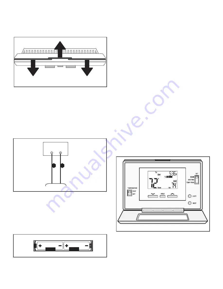
TEMPERATURE (HEAT / OFF) SWITCH:
Set this switch to
HEAT to control your appliance. The
OFF
position will disable the appliance.
SET (MULTI- FUNCTION) SLIDE SWITCH:
This provides easy access to common settings, and should
always remain in RUN unless items are being adjusted.
NOTE:
When thermostat is set to “Manual” non-program
-
mable mode, all positions of the SET slide switch
will act like RUN.
UP / DOWN BUTTONS:
The
UP
and
DOWN
buttons are used to control the set
temperature, or adjust any other on-screen items. An
items flashing, is the item currently being adjusted.
Thermostat Controls
Figure 3.13
HOLD BUTTON:
This button activates and deactivates the manual Temper-
ature
HOLD feature, which maintains a fixed set tempera
-
ture indefinitely without following a program routine.
COPY BUTTON:
This is used to copy temperature program items from one
day to the next. Also used to access the menu setup.
NEXT BUTTON:
This is used when setting items such as software options,
and temperature programs when they are flashing on the
screen. Pressing the NEXT button will cycle through which
item is flashing.
6. There are two
AA ALKALINE ONLY
batteries already
installed into the thermostat; to activate, remove black
plastic tab that is located inside the battery compart-
ment.
7. Snap the thermostat to the base plate.
W
R
W
R
Appliance
Figure 3.11
2.
Use a drill with either a 3/16 drill bit for drywall or a
7/32 drill bit for plaster drill holes.
3.
Using a hammer tap in wall anchors.
4. Route the wires through the opening in the base plate,
and hold the base against the wall while aligning up
to the holes. Attach base plate using a Phillips head
screwdriver and two screws
(C2)
.
5.
Connect your thermostat wire to the W and R termi
-
nals. See Figure 3.11.
3. Programmable Wall Thermostat Installation
Figure 3.10
1.
Separate the body of the thermostat from the mount
-
ing plate by gently pulling the two pieces apart. See
Figure 3.10.
12
Quadra-Fire • Pioneer III Owner’s Manual • 4182-900 • Rev D • 08/19


