REMINGTON QFP40 Direct Vent FIREPLACE
Page 32
250-4721 JUNE 2001
VENTING
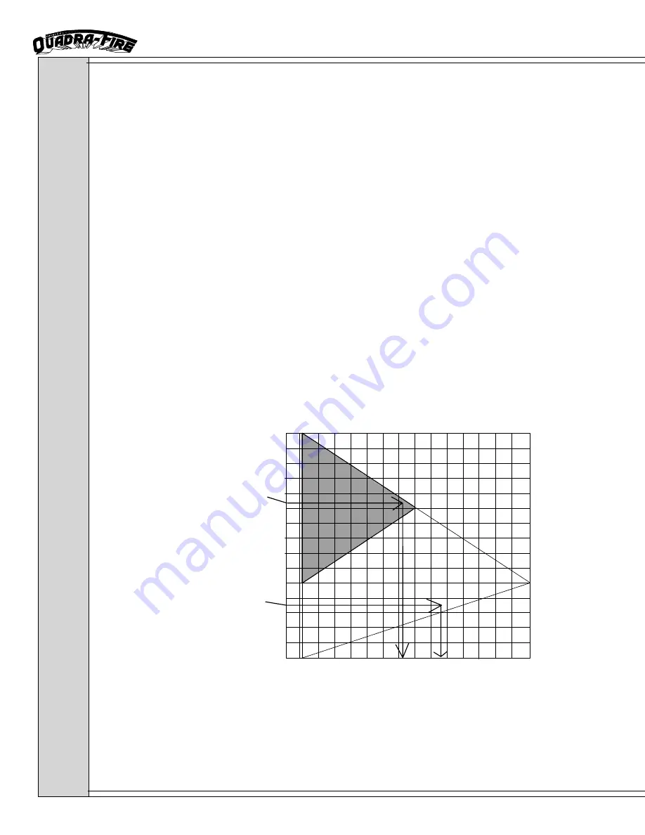
HOW TO USE VENT GRAPH
TOTAL HORIZONTAL RUN TO
OUTSIDE OF EXTERIOR WALL
(EXCLUDING ELBOWS)
2'
4'
6'
8'
10'
12'
14'
16'
18'
20'
22'
24'
26'
28'
30'
11" 2' 4' 6' 8' 10' 12' 14' 15'
(MIN) (MAX)
VERTICAL DISTANCE
FROM APPLIANCE TOP
TO THE 90° ELBOW
0'
EX. 1
Ex. 2
1. Measure the distance from the top of stove to the center of the 90° elbow. On the
graph below, draw a horizontal line from that measurement on the vertical axis across
until it intersects with the slanted line.
2. From the point of this intersection, draw a vertical line to the bottom of the graph.
3. The point at which this line meets the bottom line of the graph is the maximum length
of the horizontal run.
Example 1:
If the vertical dimension from the top of the stove to the center of the 90°
elbow is 7' (2.13m), the horizontal run to the outer wall flange must not
exceed 9' 9" (2.97m).
Example 2:
If the vertical dimension from the top of the stove is 21’ (6.4m), the hori-
zontal run to the outer wall flange must not exceed 7’ 3" (2.21m).
Note:
The maximum horizontal vent run is 15' (4.57m) when the vertical vent rise is 10'
(3.05m).
The minimum horizontal vent run is 12" (305mm).
Minimum wall thickness is 4" (102mm). Maximum wall thickness is 20" (508mm).
•
Vent damper may need to be adjusted if your installation falls in the shaded area
shown in graph.


