background image

2

04/21

7019-802H

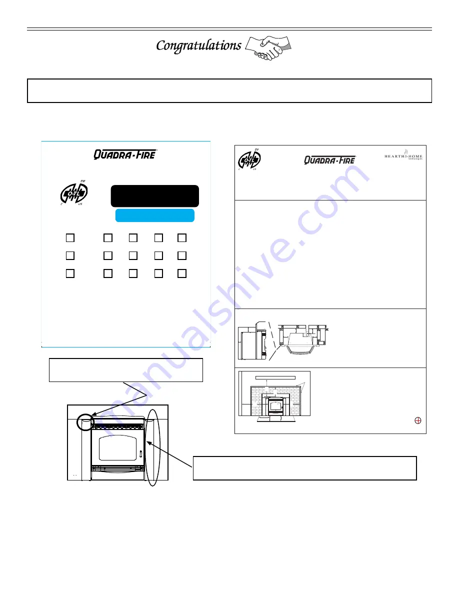
A. Sample of Serial Number / Safety Label

LOCATION: On chain behind right access panel & Behind left access panel

SAMPLE: SERIAL NUMBER LABEL

LOCATION: Behind left access panel.

SAMPLE: CLEARANCE TO COMBUSTIBLES LABEL

LOCATION: On chain behind right access panel

BARCODE LABEL

3.5

2020

2021

2022

JAN

FEB

MAR

APR

MAY

JUNE

JULY

AUG

SEPT

OCT

NOV

DEC

U.S. ENVIRONMENTAL PROTECTION AGENCY

Certified to comply with 2020 particulate emission standards at


1.1 

g/hr EPA Method 

28R and ASTM 2779 using premium wood pellets

.

Input Rating: 

30,600

 Btu’s/hr.

DO NOT REMOVE THIS LABEL / NE PAS ENLEVER L'ÉTIQUETTE

Made in China/ Fait Aux Chine

7019-799C

THIS WOOD HEATER NEEDS PERIODIC INSPECTION AND REPAIR FOR PROPER OPERATION. CONSULT THE 

OWNER’S MANUAL FOR FURTHER INFORMATION. IT IS AGAINST FEDERAL REGULATIONS TO OPERATE THIS 

WOOD HEATER IN A MANNER INCONSISTENT WITH THE OPERATING INSTRUCTIONS IN THE OWNER’S MANUAL.

Serial No. / N° de série

US

Report / Rapport:

061-S-77c-6.2

0061PM077E

SANTAFEI-C

*PSANTAFEI-C*

English

3/16 [4.8]

3/16 [4.8]

Report No. 

#061-S-77d-6.2

0061PM077E

7019-800C

SAFETY LABEL

R

352 Mountain House Road, 

Halifax, PA 17032

www.quadrafire.com

Listed Solid Fuel Room Heater/Pellet Type Insert.  Also suitable for Mobile Home Installation.  This appliance has been 

tested and listed for use in Manufactured Homes in accordance with OAR 814-23-9000 through 814-23-909.

Tested to:

 ASTM E-1509-2004 and ULC S628-93 Room Heating Pellet Burning Type, (UM) 84-HUD FOR USE ONLY WITH 

PELLETIZED WOOD OR SHELLED FIELD CORN FUEL.   Do not use any other type of fuel.  OMNI-Test Laboratories, Inc. has 

determined that this appliance complies with Canadian Standards Association (CSA) B415.1 and Title 40 of the U.S. 

Code of Federal Regulations, Part 60, SubPart AAA.OMNI-Test Laboratories Accrediations:  The Standards Council of 

Canada, the American National Standards Institute, and the U.S. Environmental Protection Agency.

Route power cord away from unit. Do not route cord under or in front of appliance.

DANGER: 

 Risk of electrical shock.  Disconnect power supply before servicing.  Replace glass only with 5mm ceramic available 

from your dealer.  

To start, set thermostat above room temperature, the appliance will light automatically.  To shutdown, set thermostat to below room 

temperature.  For further instruction refer to owner's manual. 

KEEP VIEWING AND ASH REMOVAL DOORS TIGHTLY CLOSED DURING OPERATION.

Input Rating:  

30,600

 BTU/HR. 

Electrical Rating:  115 VAC, 60 Hz, Start 4.1 Amps, Run 1.1 AMPS.

MINIMUM CLEARANCES TO COMBUSTIBLE MATERIALS

AS A BUILT-IN UNIT

A

  Top of Hopper   

       Top Vent  

     2.0 in.    51mm


        Rear Vent       2.5 in.    64mm

B

  Side of Hopper 

       Top/Rear Vent   2.0 in.    51mm

C

  Back of Hopper 

       Top/Rear Vent   2.5 in.    64mm

D

  Vent Pipe to Combustible     Top/Rear Vent    3.0 in.    76mm

A

C

B

D

C

B

0 in. Clearance To Exposed Section And Face Trim

Masonry or Zero Clearance

Max. Mantel Depth: 12 in. (305mm)

SIDE W

ALL

MANTEL

A

E

F

Face Trim

DO NOT REMOVE THIS LABEL

A

  Insert side to combustible side wall   

16 in. 

406mm

B

  Insert top to mantel   


12 in. 

305mm

C

  Insert top to max. 2.25 in. to top face trim 

4.75 in. 

121mm

D

  Insert side to max. 2.25 in. to side face trim  

10 in. 

254mm

E

  Hearth extension to from door opening - front  6 in . 

152mm

F

  Hearth extension from side of door opening 

6 in. 

152mm

*When constructing floor protection for your pellet appliance,

any parts or materials used, must be non-combustible.

PREVENT HOUSE FIRES

Install and use only in accordance with manufacturer's installation and operating instructions. CONTACT LOCAL BUILDING 

OR FIRE OFFICIALS ABOUT RESTRICTIONS AND INSTALLATION INSPECTION IN YOUR AREA.

WARNING - FOR MOBILE HOMES:

 Do not install appliance in a sleeping room. An outside combustion air inlet 

must be provided. The structural integrity of the mobile home floor, ceiling and walls must be maintained.

Refer to manufacturer's instructions and local codes for precautions required for passing chimney through a combustible 

wall or ceiling. Inspect and clean vent system frequently in accordance with manufacturer's instructions.

Do Not Connect This Unit to a Chimney Serving Another Appliance.

Use a 3" or 4" diameter type "L" or "PL" venting system.

D

B

C

SANTAFEI-C

*PSANTAFEI-C*

NOTE:

 Clearances may only be reduced by means approved by the regulatory 

authority having jurisdiction

and Welcome to the Quadra-Fire Family

!

SAMPLE

Summary of Contents for SANTAFEI-C

Page 1: ...ons is not followed exactly a fire could result causing property damage personal injury or death Do not store or use gasoline or other flammable vapors and liquids in the vicinity of this or any other...

Page 2: ...ore servicing Replace glass only with 5mm ceramic available from your dealer To start set thermostat above room temperature the appliance will light automatically To shutdown set thermostat to below r...

Page 3: ...Fuel Material and Fuel Storage 8 E Before Your First Fire 9 F Filling the Hopper 9 G General Operating Information 10 H Starting Your First Fire 10 I Fire Characteristics 11 J Feed Rate Adjustment In...

Page 4: ...ots blowers junction boxes wire harnesses transformers and lights excluding light bulbs X X Molded Refractory Panels Glass Liners X Vent Free Burners Vent Free Logs X X Castings Medallions and Baffles...

Page 5: ...overed by this warranty Limited Catalyst Warranty o For wood burning products containing a catalyst the catalyst will be warranted for a six year period to the original purchaser at catalyst WARRANTY...

Page 6: ...45 lbs Fuel Premium Wood Pellets Weighted average LHV Low Heating Value efficiency using data collected during EPA emissions tests in accordance with the requirements of CSA B415 1 Weighted average H...

Page 7: ...The size of the room must be at least 50ft per 1 000 Btu hr stove input if the stove exceeds the room size outside air must be installed H California Prop65 WARNING This product and the fuels used to...

Page 8: ...e heating appliance and close to the sleeping areas Follow the detector s manufacturer s placement and installation instructions and maintain regularly A CO detector should be installed in the room wi...

Page 9: ...ing occasionally Performance Higher ash content requires the fire pot and the ash drawer to be emptied more frequently Hardwoods require more air to burn properly Premium wood pellets produce the high...

Page 10: ...then adjust the thermostat to its highest setting The red call light will be on which is located on the front of the junction box behind the left access panel This indicates the thermostat is calling...

Page 11: ...ards the symbol to decrease the feed rate and flame height 3 Re tighten the wing nut Finger Hole in Rod Wing Nut Figure 11 3 I Fire Characteristics A properly adjusted fire with the heat output contro...

Page 12: ...dles and other heat sensitive ob jects on mantel or hearth Heat may damage these objects M Restarting the Appliance Restart Process 1 When the unit has run out of fuel add pellet fuel to the hopper 2...

Page 13: ...and is advanced to each following item by a single press of the NEXT button The options for each item are changed using the UP or DOWN buttons ITEM 01 CLK CLOCK FORMAT 12Hr default This displays the...

Page 14: ...porarily changed set temperature will return to the programmed value stored in memory when start time of the next upcoming scheduled event is reached MORN DAY EVE OR NITE While the temporary changed s...

Page 15: ...Y button to set desired days with original setting NOTE The word COPY will not appear on the display for Monday but will display each day afterwards for approximately one second and the day of the wee...

Page 16: ...adding batteries to the compartment When finished line up the front of the thermostat to the base and firmly press together to securely latch the front and back halves together properly BATTERY GRAPHI...

Page 17: ...m the impellers becoming dirty over time See maintenance and service section for maintaining and servicing What is the metal object with the bend in it that came inside the plastic bag It is a clean o...

Page 18: ...obscured OR X Heat Exchanger Drop Tube Every 1 ton of fuel OR X Hopper Every 1 ton of fuel or when changing fuel types OR X Venting System More frequently depending on the fuel type OR X This pellet...

Page 19: ...uel you are burning will dictate how often you have to clean your fire pot If the fuel you are burning has a high dirt or ash content it may be necessary to clean the fire pot more than once a day Dir...

Page 20: ...nd continue throughout the rest of the firebox c Replace right brick and baffle and close cast hinge face 9 Cleaning the Hopper Frequency Monthly or every 1 ton of fuel By Homeowner After burning appr...

Page 21: ...g Exhaust Blower Requires No Lubrication Frequency Yearly or as needed By Quality Service Technician Homeowner Remove left right brick The exhaust blower is behind the right brick Vacuum this area tho...

Page 22: ...e 22 2 The correct flame size when good quality premium pellet fuel is burned is shown in Figure 22 3 If the ash buildup exceeds the half way point in the fire pot IMMEDIATE ATTENTION AND CLEANING IS...

Page 23: ...Unburned pellets in fire pot Fire pot clean out plate not closed Fire pot is dirty The ignition hole between the igniter bracket and fire pot is blocked Igniter not working Control box defective Chec...

Page 24: ...es not shut off Blower not plugged in Blower is clogged with ash Blower is defective Control box is defective Check that blower is plugged into wire harness Clean exhaust system Replace blower Replace...

Page 25: ...Housing Bolts Blower Mounting Screws Figure 25 2 Figure 25 3 2 Convection Blower PART NUMBER 812 4900 a The blower is located at the bottom rear of the insert If an outside air kit is also installed...

Page 26: ...r left brick 3 Reinstall bricks in reverse order ensuring that the bricks are flush against the back wall of the firebox Figure 26 4 and Figure 26 5 Figure 26 1 Brick is flush against back wall Brick...

Page 27: ...ash drawer and then re install the side panel and re connect the power Figure 27 1 Igniter Igniter Bracket Thumb Screw E Glass PART NUMBER SRV7021 032 1 Open the face and remove door from the applian...

Page 28: ...utomatically start blinking 6 blinks every 10 seconds for 60 seconds and then will stop 8 Heat Output Switch The heat output switch is located on the lower right side of firebox in front of the right...

Page 29: ...he auger tube in the center of the appliance and has a reset button To access it remove the right side panel If the fire tries to burn back into the feed system or push exhaust up the feed tube this s...

Page 30: ...Terminal Block Center 2 Screws for Thermostat Wires or Remote 110 Outlet for Remote Control Only unfused Fuse Red Call Light Outside Air Inlet Figure 30 1 Cleaning Rods Heat Exchanger Tubes Figure 30...

Page 31: ...31 04 21 7019 802H C Service Maintenance Log Date of Service Performed By Description of Service...

Page 32: ...32 04 21 7019 802H Date of Service Performed By Description of Service...

Page 33: ...33 04 21 7019 802H Date of Service Performed By Description of Service...

Page 34: ...C Beginning Manufacturing Date Apr 2019 Ending Manufacturing Date Active Pellet Insert Part number list on following page 04 21 1 2 3 4 5 6 7 8 9 10 11 12 13 14 15 16 17 18 19 20 21 22 23 24 25 26 27...

Page 35: ...7019 189 Nickel SRV7019 162 6 Grill Bracket Cover 7019 199 7 Lower Grill Assembly 4 Pc Black 7019 008 Black Nickel 7019 190 Nickel SRV7019 163 8 Ash Draw Assembly 7019 006 9 Face Assembly w Door SRV7...

Page 36: ...ge Gasket SRV7036 180 Latch Draw 229 0230 24 Flue Collar Assembly 7019 031 25 Blower Convection 812 4900 Y Blower Magnet Pkg of 10 7019 188 10 26 Outer Skin Back SRV7019 101 27 Feed Assembly 812 4760...

Page 37: ...d Black Nickel SRV7019 172 Spring Firepot 200 2050 36 3 Heating Element Assembly 18 Loop Igniter Pkg of 10 SRV7000 462 10 Y 36 4 Firepot Assembly SRV414 5200 Y Bolt Firepot 1 1 4 Long Pkg of 25 225 01...

Page 38: ...Log Rear Left 7050 144 Log Rear Right 7050 143 Outside Air Kit Rear 811 0872 Channel Air Intake SRV413 7040 Cover Outside Air Kit Floor 411 1071 Hose Alum Flex 2 Inch X 3 Ft SRV200 0860 Outside Air C...

Page 39: ...Nut Wing 1 4 20 Pkg of 12 226 0110 12 Nut Wing 8 32 Pkg of 24 226 0160 24 Y Pin 3 16 X 1 2 7000 229 Rivet Iron 1 4 X 1 1 4 Pkg of 25 229 0090 25 Screw Flat Head 1 4 20 Pkg of 24 7000 130 24 Y Screw F...

Page 40: ...maintenance instructions included Read understand and follow these instructions for safe installation and operation Leave this manual with party responsible for use and operation of this appliance We...

Reviews: