background image

 12 


                          7019-230C 


                 May 18, 2015

Santa Fe Pellet Insert

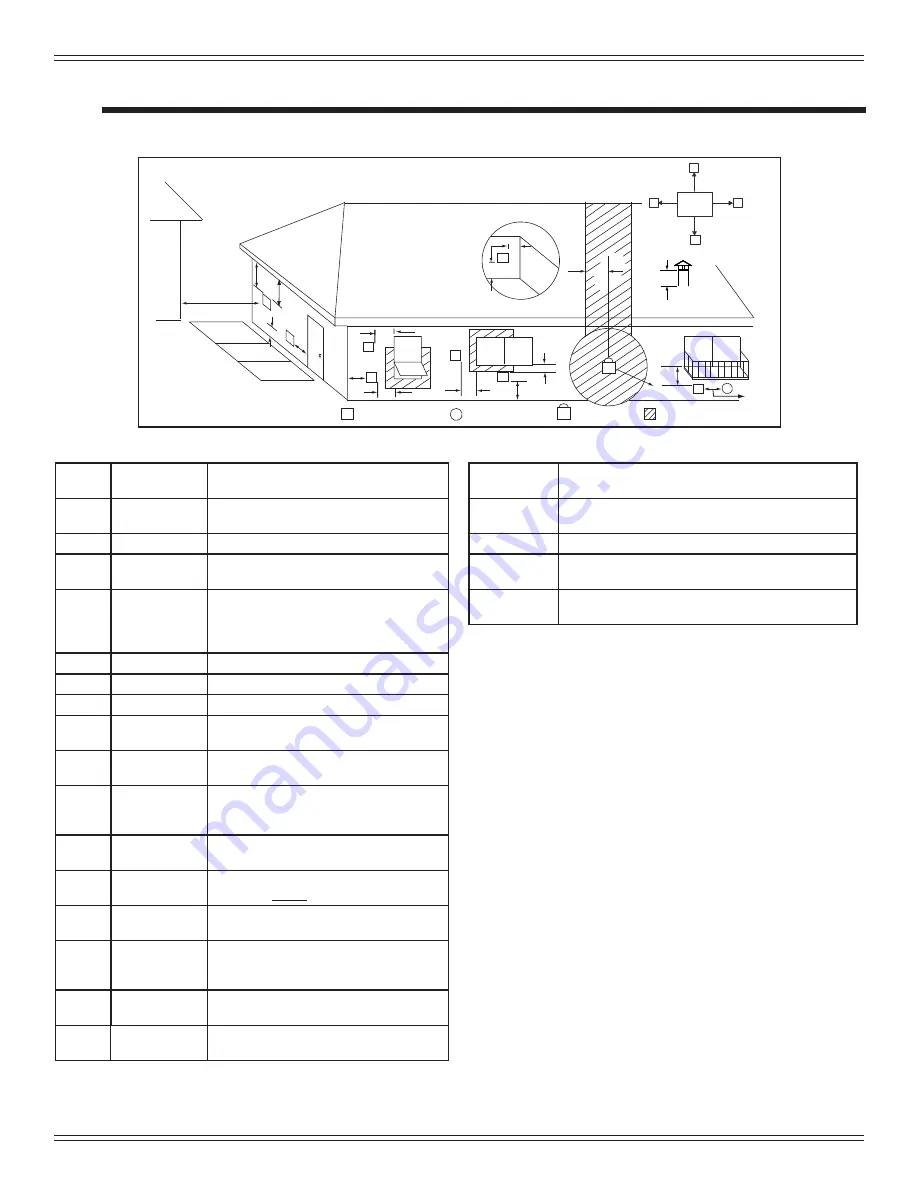
Vent Information

A.  Venting Termination Minimum Requirements

J or K

X

V

M

I

H

A

V

G

B

V

V

A

B

V

F

V

C

B

B

E

L

V

D

V

Electrical

Service

V

N

V

N

V

N

N

V

Inside Corner

FIXED 
CLOSED

OPEN

OPEN

FIXED 
CLOSED

V

X

G

G

Termination Cap

Air Supply Inlet

Gas Meter

Restricted Area

O

P

Figure 11.1

A

12 in.

Above Finish Grade (the grade surface 
must be a non-combustible material

B

12 in.
48 in. no OAK

Open door or window: below or to the side

B

12 in.

Open door or window: above

C

6 in.

Permanently closed window: above, below 
or to the side

D

18 in.
36 in. no OAK

Vertical clearance to a ventilated soffi t 
located above the terminal within a hori-
zontal distance of 2 ft from the center-line 
of the terminal 

E

12 in.

Clearance to unventilated soffi t

F

12 in.

Clearance to outside corner

G

12 in.

Clearance to inside corner

H

36 in.

Above gas meter/regulator measured from 
horizontal center-line of regulator

I

36 in. USA
72 in. Canada

Clearance to service regulator vent outlet

J

12 in.
48 in. no OAK

Clearance to non-mechanical air supply 
inlet to the building or the combustions air 
inlet to any other appliance

K

10 ft horizontal
3 ft vertical

Clearance to mechanical air supply

L

7 ft.

Above paved sidewalk, paved driveway 
located on 

public

 property

M

12 in.

Under an open veranda, porch, deck or 
balcony

N

See Note 
below*

Electric service: above, below or to the 
side (location must not obstruct or interfere 
with access)

O

24 in.

Adjacent building, fences and protruding 
parts of the structure

P

12 in.

Clearance above roof line for vertical 
terminations

All minimum clearances are listed with an Outside Air Kit (OAK) installed, unless otherwise noted in table below.

24 in.

Above grass, top of plants, wood or any other com-
bustible

12 in.
36 in. no OAK

Clearance from any forced air intake of other appli-
ance

12 in.

Clearance horizontally from combustible wall

15 in.

Vented directly through a wall, minimum length of 
horizontal pipe

6 in. horizontal
12 in. vertical

Minimum horizontal or vertical terminations must 
protrude from wall

*NOTE: 

 Consult local building, fi re offi cials or authorities having jurisdic-

tion.  Local codes or regulations may require different clearances.

NOTICE:

Do NOT Terminate Vent:

• 

In any location that will allow fl ue gases or soot from en-
tering  or staining the building

•  In any location which could create a nuisance or hazard

• 

In any enclosed or semi-enclosed area such as a carport, 
garage, attic, crawl space, under a sun deck or porch, 
narrow walkway 

•  Closely fenced area, or any location that can build up 

a concentration of fumes such as a stairwell, covered 
breezeway, etc.

NOTICE:

Termination must exhaust above air inlet elevation.  

•  It is recommended that at least 60 inches (1.52m) of vertical 

pipe be installed when appliance is vented directly through a 
wall.  This will create a natural draft, which will help prevent 
the possibility of smoke or odor venting into the home during 
a power outage. 

•  It will also keep exhaust from causing a nuisance or hazard 

by exposing people or shrubs to high temperatures.  

•  The safest and preferred venting method is to extend the vent 

vertically through the roof or above the roof.

Summary of Contents for SANTAFEI-MBK

Page 1: ...c tions is not followed exactly a fire could result causing property damage personal injury or death Do not store or use gasoline or other flam mable vapors and liquids in the vicinity of this or any other appliance Do not overfire If heater or chimney con nector glows you are overfiring Overfiring will void your warranty Comply with all minimum clearances to combustibles as specified Failure to c...

Page 2: ...sions and Clearances 7 A Appliance Dimensions 7 B Clearance To Combustibles UL and ULC 8 C Masonry and Zero Clearance Fireplaces 9 D Minimum Opening for Masonry and Zero Clearance Fireplaces 9 E Hearth Extension 9 F Floor Protection 9 G Installation into a Factory Built Fireplace 10 H Installation into a Masonry Fireplace 11 I Prefabricated Metal Chimney 11 4 Vent Information 11 A Venting Terminat...

Page 3: ...f this appliance reserves the right to alter its products their specifications and or price without notice Improper installation adjustment alteration service or maintenance can cause injury or property damage For assistance or additional information consult a qualified installer service agency or your dealer Quadra Fire is a registered trademark of Hearth Home Technologies Installation and use of...

Page 4: ...ppliance and chimney will affect performance Consideration must be given to Safety convenience traffic flow Placement of the chimney and chimney connector and to minimize the use of chimney offsets Place the appliance where there will be a clear passage for a Listed chimney through the ceiling and roof vertical or through exterior wall horizontal Installing the required outside air kit will affect...

Page 5: ...Thermostat Wall Control Location The thermostat wall control s location will have some affect on the appliance s operation Maximum wire length from appliance is 100 feet 30 48m continuous unspliced wire Recommended 20 gauge wire solid copper When located close to the appliance it may require a slightly higher temperature setting to keep the rest of the house comfortable When located in an adjacent...

Page 6: ...inimum height requirements Roof flashing installed and sealed Terminations installed and sealed Clearances Section 3 Pg 7 Combustible materials not installed in non combustible areas Verified all clearances meet installation manual requirements Mantels and wall projections comply with installation manual requirements Protective hearth strips and hearth extension installed per manual requirements A...

Page 7: ...7 1 Top View Figure 7 2 Side View 21 1 2 546mm 28 7 8 733mm 23 5 8 600mm 8 203mm C L 12 3 4 324mm 8 5 8 219mm 23 584mm 25 3 8 645mm Panel A B Standard 40 inches 1016mm 30 inches 762mm Large 50 inches 1270mm 33 inches 838mm A B 3 Dimensions and Clearances A Appliance Dimensions ...

Page 8: ... D C B 0 in Clearance To Exposed Section And Face Trim C L B Clearance To Combustibles UL and ULC Inches Millimeters A Top of Hopper Top Vent 2 0 51 Rear Vent 2 5 64 B Side of Hopper Top or Rear Vent 2 0 51 C Back of Hopper Top or Rear Vent 2 5 64 D Vent Pipe to Combustible Top or Rear Vent 3 0 76 12 in 305mm Combustible Mantel 6 in 152mm Outside Air Top Vent 2 in 51mm Rear Vent 2 5 in 64mm Back o...

Page 9: ... Depth 16 406 C Height 23 1 4 591 D Front Width 29 1 4 743 Figure 9 1 C Masonry and Zero Clearance Fireplaces Inches Millimeters E Floor protection hearth extension from door opening 6 152 F Floor protection to the side of door opening 6 152 F Floor Protection Figure 9 2 Side Wall Mantel Maximum Mantel Depth 12 inches 305mm Face Trim E F A D C B NOTE It is necessary to permanently seal any opening...

Page 10: ...t the insert The 2 x 4 may need to be cut to the appro priate size 250 2061 WARNING THIS FIREPLACE MAY HAVE BEEN ALTERED TO ACCOMMODATE AN INSERT IT MUST BE RETURNED TO ITS ORIGINAL CONDITION BEFORE USE AS A SOLID FUEL BURNING FIREPLACE 250 2061 Figure 10 1 If the hearth extension is lower than the fireplace opening the portion of the insert extending onto the hearth must be supported Manufacturer...

Page 11: ...oved chimney liner meeting type UL 103 HT requirements 2100 F per UL 1777 If the chimney is not listed as meeting HT requirements or if the factory built fireplace was tested prior to 1998 a full height listed chimney liner must be installed from the appliance flue collar to the chimney top The liner must be securely attached to the insert flue collar and the chimney top The air flow of the factor...

Page 12: ...ces and protruding parts of the structure P 12 in Clearance above roof line for vertical terminations All minimum clearances are listed with an Outside Air Kit OAK installed unless otherwise noted in table below 24 in Above grass top of plants wood or any other com bustible 12 in 36 in no OAK Clearance from any forced air intake of other appli ance 12 in Clearance horizontally from combustible wal...

Page 13: ... wall as the exhaust vent outlet and located lower on the wall than the exhaust vent outlet The outside air supply kit can supply most of the demands of the pellet appliance but consideration must be given to the total house demand House demand may consume the air needed for the appli ance It may be necessary to add additional ventilation to the space in which the pellet appliance is located Consu...

Page 14: ...d chimney NOTICE Hearth Home Technologies assumes no responsibility for the improper performance of the chimney system caused by Inadequate draft due to environmental conditions Downdrafts Tight sealing construction of the structure Mechanical exhausting devices E Chimney and Exhaust Connection 1 Chimney Connector Use 3 or 4 inch 76 102mm diameter type L or PL venting system It can be vented verti...

Page 15: ...tible shielding or guards may be required WARNING Figure 14 2 3 in or 4 in 76mm or 102mm Diameter Pipe Equivalent Pipe Length In Feet ALTITUDE IN THOUSANDS OF FEET 0 20 30 1 2 3 4 5 6 7 8 9 10 4 in 102mm Diameter Pipe Only 10 Example 1 Example 2 Example 1 If the equivalent length of pipe is 23 feet 7m with altitude of 8 000 feet 2438m you must use 4 inch 102mm diameter type L or PL vent Example 2 ...

Page 16: ...ir from Wall floor or ceiling cavity Enclosed space such as an attic or garage NOTE Illustrations reflect typical installations and are FOR DESIGN PURPOSES ONLY Illustrations diagrams are not drawn to scale Actual installation may vary due to individual design preference Outside Air through Rear Wall Horizontal NOTE Use metal plate around exhaust vent pipe and seal all edges with non flammable ins...

Page 17: ...e 16 2 NOTE In Canada only a full reline is allowed per ULC S628 93 ORD ULC C1482 M1990 NOTE In Canada this fireplace insert must be installed with a continuous chimney liner extending from the fire place insert to the top of the chimney The chimney liner must conform to the Class 3 requirements of CAN ULC S635 Standard for Lining Systems for Existing Masonry or Factory Built Chimneys and Vents or...

Page 18: ...e distance from floor to air vent opening in appli ance and mark location on wall 2 Use saw to cut opening in wall Cut a 2 1 2 to 3 inch 64 76mm opening on inside wall and a 3 to 3 1 2 inch 76 89mm opening on outside of house 3 Use hose clamp to secure flex pipe to collar assembly 4 Slide trim ring over flex pipe and run pipe through wall 5 Attach hose to outside termination cap with second hose c...

Page 19: ...led on the appliance they are then finger bent into position 4 Attach the 4 grille bracket covers to the lower 4 grilles and the top 3 grilles Slip the metal strips through the grille openings and secure to grille with screws provided Do not finger bend the cover brackets at this time 5 Secure the lower grille to the appliance with 2 screws on each side Finger bend the bracket covers around the pl...

Page 20: ...ifficult once trim has adhered to tape Do a dry run first without removing paper from tape 6 Place cut edge of trim under top lip and into position on scissors Place side pieces on first and then front piece The front piece overlaps side pieces 7 Once you are satisfied with the positioning remove trim and set aside 8 Remove the paper from double sided tape that is to accept trim side Align side an...

Page 21: ... access panel there are 2 hooks that slip into a slot at the bottom of the side panel and a magnet at the top that holds the access panel in place Figure 20 3 Attach panel legs to top Back view of panel Access Panel Side Panel H Thermostat Installation 1 A 12 volt AC thermostat is required to operate this pellet appliance You may use the included wall mount thermo stat or purchase an optional prog...

Page 22: ... to maintain the desired tem perature in your home 3 There is a 4 screw terminal block located on the junction box to the right of the power cord inlet The center 2 screws are for the thermostat wires The outer 2 are the mounting screws for the terminal block Figure 21 1 Figure 21 1 Figure 21 2 I Optional Log Set Placement Two Piece Log Set Installation 1 Open door to expose the firebox 2 Install ...

Page 23: ...d HUD CFR 3280 Part 24 NEVER INSTALL IN A SLEEPING ROOM WARNING Spark Arestor Cap Roof Flashing Storm Collar Joist Shield Firestop Double Wall Connector Pipe Figure 22 1 CAUTION Never draw outside combustion air from Wall floor or ceiling cavity Enclosed space such as an attic or garage CAUTION THE STRUCTURAL INTEGRITY OF THE MOBILE HOME FLOOR WALL AND CEILING ROOF MUST BE MAINTAINED Do NOT cut th...

Page 24: ... Plate Outside Air Kit 412 7100 Panel Set Large Black Nickel SP SFI3350 NB No longer available SP SFI3350 GD Nickel SP SFI3350 NL Bracket L Trim 832 0840 Logo Quadra Fire Pkg of 10 7000 649 10 Trim Panel Set Black Nickel 7019 027 Gold 250 4660 Panel Set Small Black Nickel SP SFI3040 NB No longer available SP SFI3040 GD Nickel SP SFI3040 NL Bracket L Trim 832 0840 Logo Quadra Fire Nickel 7000 649 1...

Page 25: ...May 18 2015 7019 230C 25 Santa Fe Pellet Insert ...

Page 26: ...26 7019 230C May 18 2015 Santa Fe Pellet Insert ...

Page 27: ...May 18 2015 7019 230C 27 Santa Fe Pellet Insert ...

Page 28: ...ville WA 99114 Division of HNI INDUSTRIES Please contact your Quadra Fire dealer with any questions or concerns For the number of your nearest Quadra Fire dealer log onto www quadrafire com This product may be covered by one or more of the following patents United States 5341794 5263471 6688302 7216645 7047962 or other U S and foreign patents pending We recommend that you record the following pert...

Reviews: