background image

September 1, 2008

Page  15

Quadra-Fire · Topaz · 7009-113G

Step 1. 

Check the installation instructions for required 1 in. (25mm) 
clearances (air space) to combustibles when passing 
through ceilings, walls, roofs, enclosures, attic rafters, or 
other nearby combustible surfaces.  See page 16, 

Figure 

5.16. 

  Check the instructions below for maximum vertical rise 

of the venting system, and any maximum horizontal offset 
limitations. All offsets must fall within the set parameters of 
the vent graph (

Figure 5.2

) located on page 11.

NOTE: 

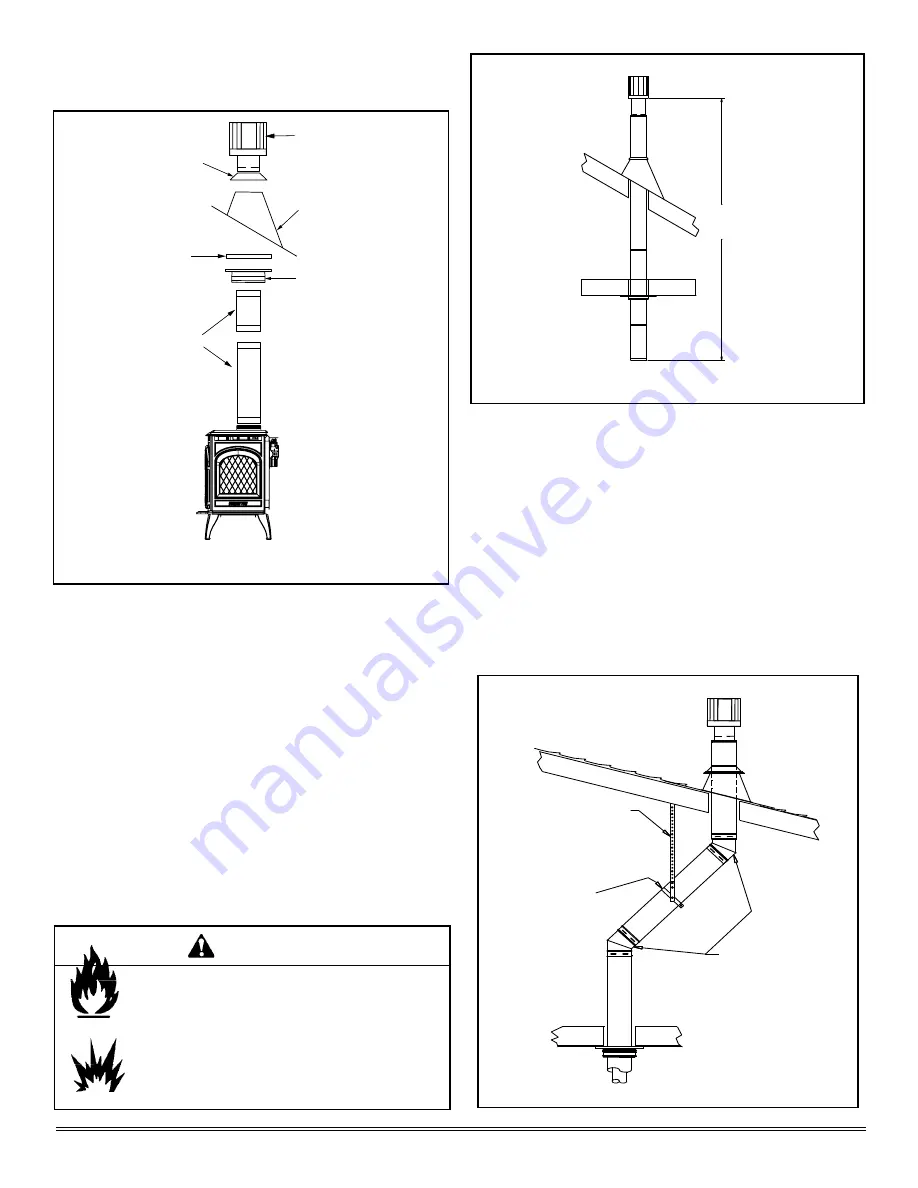
 Maximum vertical rise allowable is 40 ft. (12m) 

Fi

gure 5.11

).  

NOTE

:  Maximum number of 45° elbows permitted for a 

vertical installation is eight, provided their installation 
does not decrease maximum allowable horizontal run (as 
specified by vent graph, on page 11). 

Plumber’s Tape
connected to 
Wall Strap

Wall Strap

Two 45˚ Elbows

Step 2.

S

et the gas appliance in its desired location. Drop a plumb 

bob down from the ceiling to the position of the appliance 
flue exit, and mark the location where the vent will penetrate 
the ceiling. Drill a small hole at this point. Next, drop a plumb 
bob from the roof to the hole previously drilled in the ceiling, 
and mark the spot where the vent will penetrate the roof. 
Determine if ceiling joists, roof rafters, or other framing will 
obstruct the venting system. You may wish to relocate the 
appliance, or to offset, as shown in 

Figure 5.12

 to avoid 

cutting loadbearing members. When location is determined, 
drill small hole.

G.  Vertical Termination

1. Direct Vent Pipe

Figure 5.10  

Figure 5.11  

Figure 5.12 

Vertical Termination Cap

Storm Collar

Flashing

Firestop

Pipe Length

Support Box


40 ft. (12m) 

Maximum

Fire Risk.

Explosion Risk.

Maintain vent clearance to combustibles as speci-
fied.

WARNING

•  Do not pack air space with insulation or other 

materials.

Failure to keep insulation or other materials away 
from vent pipe may cause fire.

Summary of Contents for TOPAZ Direct Vent Room Heater 839-1290

Page 1: ...n may result causing property damage personal injury or death This appliance may be installed as an OEM installation in manufactured home USAonly or mobile home and must be installed in accordance wit...

Page 2: ...par un technicien qualife et ou muni d une licence de mani re respecter les r glements municipaux Dans la R publique de Massachusetts l installation doit tre effectu e par un plombier ou un installat...

Page 3: ...as Information A Fuel Conversions 23 B Gas Pressures 25 C Gas Connection 26 Section 7 Electrical Information A Recommendation for Wire 27 B Connecting to the Appliance 27 C Standing Pilot Ignition Sys...

Page 4: ...ING Do NOT use this appliance if any part has been under water Immediately call a quali ed service technician to inspect the unit and to replace any part of the control system and any gas control whic...

Page 5: ...ent terminal for the horizontally vented gas fueled heating appliance or equipment The sign shall read in print size no less than one half 1 2 inch in size GAS VENT DIRECTLY BELOW KEEP CLEAR OF ALL OB...

Page 6: ...ive surface See page 34 Remove log set and component pack from rebox Report to your dealer any parts damaged in shipment particularly the condition of the glass Read all of the instructions before sta...

Page 7: ...ll appliance to all clearance speci cations in manual WARNING B Clearances Figure 3 1 Model A B C D E F G Topaz Inches 6 1 2 6 1 54 36 40 23 Millimeters 165 152 25 1372 914 1016 584 NOTE Flooring bene...

Page 8: ...aintain vent clearance to combustibles as speci ed WARNING Do not pack air space with insulation or other materials Failure to keep insulation or other materials away from vent pipe may cause re HORIZ...

Page 9: ...MIN RMAX 1 cap 3 feet 2 x Q ACTUAL 2 caps 6 feet 1 x Q ACTUAL 3 caps 9 feet 2 3 x Q ACTUAL 4 caps 12 feet 1 2 x Q ACTUAL QMIN termination caps x 3 RMA X 2 termination caps xQACTUAL N 6 inches non viny...

Page 10: ...NING Diagonal runs have both vertical and horizontal vent aspects when calculating the effects Use the rise for the vertical aspect and the run for the horizontal aspect See Figure 5 1 Two 45 elbows m...

Page 11: ...is 20 ft 6m when the vertical vent rise is 10 ft 3m The minimum horizontal vent run is 6 in 152mm Horizontal sections require a 1 4 in 6mm rise for every 12 in 305mm of horizontal travel Exterior Vent...

Page 12: ...et a twist lock adapter is built into the appliance at the factory Wall thickness may vary Remember to include wall thickness in minimum clearances when figuring venting lengths for your installation...

Page 13: ...If the snorkel termination must be installed below grade i e basement application proper drainage must be provided to prevent water from entering the snorkel termination Do not backfill around snorke...

Page 14: ...tal top to vinyl standoff SCREWS Apply sealant to all four sides VINYL SIDING Figure 5 8 8 in 203mm 7 in 178mm 7 in 178mm 6 in 152mm Figure 5 7 NOTE Some termination caps may cause the vent pipe to be...

Page 15: ...bows Step 2 Set the gas appliance in its desired location Drop a plumb bob down from the ceiling to the position of the appliance flue exit and mark the location where the vent will penetrate the ceil...

Page 16: ...code requirements as outlined in the current CAN CGA B149 Installation Codes in Canada the National Fuel Gas Code NFPA 54 ANSI Z223 1 in USA or local codes Note that for steep roof pitches the vent he...

Page 17: ...be framed and sheetrocked with standard construction materials however refer to these installation instructions for the minimum allowable clearance between the outside of the vent pipe and the combus...

Page 18: ...f sheathing Step 5 Using tin snips cut the support box from the top corners down to the roofline and fold the resulting flaps over the roof sheathing Figure 5 18 Before nailing it to the roof run a be...

Page 19: ...n 76mm Connect the flex pipe to the retro connector and attach with sheet metal screws Step 6 Push the flex pipe back up into the ceiling support box center the retro connector and attach it to the su...

Page 20: ...mm Flex Liner Pipe Length Optional Chimney Liner Termination Cap Co Axial to Co Linear Connector 30 ft 9m of 3 in 76mm Flex Liner Exhaust Section Pipe Length Optional 4 ft 1m of 3 in 76mm Flex Liner A...

Page 21: ...this length extended to its nominal length Be sure to leave 2 3 in 51 76mm of flex above the existing chimney to allow for connection to the termination kit Step 3 Secure the flashing to the top of t...

Page 22: ...Secure the top adapter to the flashing Use three sheet metal screws through the side of the top adapter into the flange on the flashing Figure 5 28 Twist lock the high wind termination cap on to the t...

Page 23: ...urner by rst remov ing the two screws indicated and lifting the burner out Figure 6 3 Remove the three screws on the front of the burner support Set screws aside Figure 6 5 Remove the main burner ori...

Page 24: ...and adapter cap Fire Risk Explosion Risk Disconnect any electrical cords and turn off gas supply to unit before proceeding if converting fuel on an appliance already fully installed WARNING Replace pi...

Page 25: ...below Proper input pressures required for optimum appliance per formance gas line sizing requirements need to be followed from NFPA51 WARNING Fire Risk Explosion Hazard High pressure will damage valv...

Page 26: ...th local building codes if any If not follow ANSI Z223 1 Instal lation should be done by a quali ed installer approved and or licensed as required by the locality In the Commonwealth of Massachusetts...

Page 27: ...ermostat see individ ual thermostat instructions to ensure proper operation of appliance 4 Use low resistance thermostat wire for wiring from igni tion system to the wall switch and thermostat 5 Use t...

Page 28: ...ng controls Wiring errors can cause improper and dangerous operation Verify proper operation after servicing Shock hazard Replace damaged wire with type 105O C rated wire Wire must have high temperatu...

Page 29: ...adapter before installing as indicated in Figure 8 6 Figure 8 2 Remove inner collar adapter KIT CONTENTS Rear vent grille TOOLS REQUIRED Power drill 2 Phillips bit high temp silicone sealant optional...

Page 30: ...Home Technologies approved accessories may be used safely WARNING C Leg Leveling System Figure 8 8 Thread Allen bolts through nuts until ush The Allen bolts and nuts are included in the component pac...

Page 31: ...TRUCTIONS FOR QUARTET AND SOLITAIRE FACE OPTIONS Figure 8 11 Solitaire Front Quartet Front Spacer NOTE The brick supplied with the Topaz is not an optional accessory The brick must be installed for sa...

Page 32: ...talled side panel and support the other end with one hand Install the remaining side panel and bend over the tabs to hold it in place Rest top panel baf e on sides and slide top panel baf e left or ri...

Page 33: ...omplete your log set applica tion reinstall the glass and the front of the unit H Mineral Wool Follow ember placement instructions in manual Do NOT place embers directly over burner ports Replace embe...

Page 34: ...ckaging Place blower under appliance Attach blower from front with 4 screws to blower bracket Figure 8 27 Install snap disc in bracket Attach bracket to re box with 5 16 in wrench Figure 8 28 Connect...

Page 35: ...08 Page 35 Quadra Fire Topaz 7009 113G Figure 8 31 Blower Wiring Diagram Fan Speed Control Thermal Disc 110 VAC Power Cord BLAC K Bushing Strain Relief GREEN BLACK Ground Fan Assembly BLACK BLACK WHIT...

Page 36: ...wingnut to lock in place K Damper Adjustment Make adjustment Let appliance warm up before adjusting Loosen screw using a Phillips head screwdriver Pivot the vertical damper adjustor in 1 4 in 6mm incr...

Page 37: ...the baf e adjustment Ensure that there are no gas leaks Ensure that the glass is sealed and in the proper posi tion Ensure that the ow of combustion and ventilation air is not obstructed front grille...

Page 38: ...r of the appliance May need to remove face front first 5 Push in gas control knob slightly and turn clockwise to the OFF position Do not force 6 Wait five 5 minutes to clear out any gas Smell for gas...

Page 39: ...detectors Smoke and odors may be irritating to sensitive individuals CAUTION Prevent accidental appliance operation when not attended Unplug or remove batteries from remote control if absent or if ap...

Page 40: ...e thermocouple connection at the gas valve is fully inserted and tight hand tighten plus 1 4 turn Disconnect the thermocouple from the valve place one millivolt lead wire on the tip of the thermocoupl...

Page 41: ...g exhaust gases back into the system Check for proper vent connection at ue collar and all vent joints c Horizontal vent improperly pitched The horizontal vent cap should slope down only enough to pre...

Page 42: ...ratching or slamming glass Do NOT use abrasive cleaners Use a hard water deposit glass cleaner on white lm Do NOT clean glass when hot Turn off appliance after 3 4 hours of operation and ALLOW TO COOL...

Page 43: ...aint as neces sary 2 Replace appliance if rebox has been perforated Burner Ignition and Operation 1 Verify burner is properly secured and aligned with pilot or igniter 2 Clean off burner top inspect f...

Page 44: ...for reference only For clearances refer to Section 3 Figure 12 1 Appliance Dimensions B C A K L M N O D E F G H I J Location Inches Millimeter Location Inches Millimeter A 27 3 8 695 I 19 3 8 492 B 7...

Page 45: ...9 1 4 in 235mm 6 1 2 in 165mm 6 5 8 in 168mm 17 24 in 432 610mm 11 3 4 in 298mm 5 3 4 in 146mm 6 5 8 in 168mm 6 3 8 in 162mm 6 1 2 in 165mm 9 5 8 in 244mm 6 5 8 in 168mm 6 1 2 in 165mm 6 3 8 in 162mm...

Page 46: ...vanized SLP48M 46 DVA 48 4DT 48 4D4 SV4L48 48 Pipe Length Black SLP48 BK 46 DVA 48B 4DT 48B 4D4B SV4LB48 Adjustable Length 3 6 Black SLP6A BK Adjustable Length 3 6 Galvanized SLP6AM Adjustable Length...

Page 47: ...e Roof Flashing 4 to 8 pipes 6 RF4 8M Storm Collar SLP SCM 46DVA SC 4DT SC 4DSC SV4FC Trim Plate Black 4DT TP 4DFPB SV4LA Wall Support Band SLP HVSM 46 DVA WS 4DT WS B 4DWS SV4BM Wall Thimble Support...

Page 48: ...r Retainer Assembly 20 Igniter Piezo 3 Door Assembly 12 Side Kit 21 Switch Bracket 4 Burner Assembly 13 Valve Bracket 22 Grille Rear Vent 5 Pilot Assembly 14 Back Shield Lower 23 Grille Top Vent 6 Ref...

Page 49: ...ting Bracket Bottom 7009 102 25 Cast Mounting Bracket Top 7009 101 Component Pack Includes ON OFF Valve Mineral Wool Pilot Injector EZ LP 35 Conversion Regulator S I T LP LP Ori ce 073 Conversion Labe...

Page 50: ...in 200 2940 Flex Line 3 8 Flare x 22L 7000 197 Gasket Cover Plate 7010 160 Gasket Elbow 460 0610 Glass Assembly 7011 015 22 Grille Rear Vent Matte Black 844 9830 22 Grille Rear Vent Porcelain Cr me 8...

Page 51: ...art below Topaz Shipping Kit 842 5140 13 Valve Bracket 7009 104 15 Valve S I T LP 842 0230 15 Valve S I T NG 842 0240 Wire Harness 7009 114 IMPORTANT THIS IS DATED INFORMATION The most current informa...

Page 52: ...celain Mahogany 844 9810 Warming Shelves Porcelain Midnite Blue 844 9821 Warming Shelves Powder Coat Creme WSLG CCR Warming Shelves Powder Coat Linden Green WSLG CLG IMPORTANT THIS IS DATED INFORMATIO...

Page 53: ...September 1 2008 Page 53 Quadra Fire Topaz 7009 113G F Service and Maintenance Log Date of Service Performed By Description of Service...

Page 54: ...onditions Exclusions and limitations 9 01 08 CONDITIONS EXCLUSIONS LIMITATION OF LIABILITY This warranty applies to the original owner and is transferable up to two years from date of purchase to the...

Page 55: ...ine uorine or other damaging chemicals the appliance is subject to prolonged periods of dampness or condensation or there is any damage to the appliance or other components due to water or weather dam...

Page 56: ...This product may be covered by one or more of the following patents United States 4593510 4686807 4766876 4793322 4811534 5000162 5016609 5076254 5113843 5191877 5218953 5263471 5328356 5341794 534798...

Reviews: