background image

2

EN

3

Contents

Safety instructions  

3-4

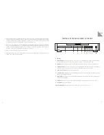
Controls fitted on the front of the unit 

5

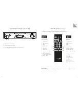
Connections on the back of the unit 

6

Remote control (OPTIONAL) 

7

Ambient conditions 

8

Installing 9
Specifications 10


Inhalt

Sicherheitshinweise 11-12
Bedienelemente an der Gerätevorderseite 

13

Anschlüsse auf der Geräterückseite 

14

Fernbedienung 15
Umgebungsbedingungen 16
Inbetriebnahme 17
Technische Daten 

18

Sommaire

Indications de sécurité 

19-20

Éléments de commande sur l‘avant de l‘appareil 

21

Connexions sur l‘arrière de l‘appareil 

22

Télécommande (EN OPTION) 

23

Conditions d‘environnement 

24

Mise en service 

25

Caractéristiques techniques 

26

Índice

Instrucciones de seguridad 

27-28

Elementos de control en el lado delantero 
del aparat 

29

Conexiones en el lado posterior del aparato 

30

Mando a distancia (OPCIONAL) 

31

Condiciones ambientales 

32

Puesta en servicio 

33

Datos técnicos


34 

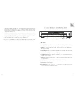
We would like to congratulate you on your decision to purchase our AURUM C8 CD-player. We 
manufacture top-quality HiFi equipment which we hope will delight you each time you use it. Our goal in 
all of this is to truly satisfy the requirements of music lovers just like you.
Even though you may already be knowledgable in using this type of equipment, we’d still like to introduce 
some basic rules and guidance that will enable you to get the best out of your purchase. Please do take 
a few moments to read this information.

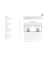
SAFETY INSTRUCTIONS 

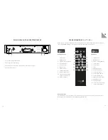
Please read through these instructions carefully and follow all of the steps listed here for installing the 

equipment. You must abide by all of the warnings and safety instructions that are stipulated on the unit 

and in this instruction manual. Keep this manual close to hand so that you can consult it if you have any 

questions later on.

•  The mains power cable and other connecting cables must be laid so that none of them are crushed or 

damaged by furniture, are being trodden on, and / or that nobody will trip over them.

•  Take the power plug out of the socket during lightening storms or if the equipment will not be used for 

a long time. Always pull the plug out of the socket and never remove it by pulling on the cable!

•  Never use the equipment in the vicinity of water, in humid areas or outdoors. Moisture can bypass the 

electrical insulation and this will create a life-threatening risk as is the case with all equipment that has 

not been specially designed against the penetration of moisture.

•  Protect the equipment against water being sprayed on it. You must also ensure that no vessels 

containing liquid (e.g. vases) are placed on top of the equipment.

•  Do not place the equipment in the vicinity of a heat source such as an electric fire, radiator, oven or 

similar.

•  The slits and openings in the enclosure provide the ventilation and ensure reliable operation. They 

must never be misaligned or covered.

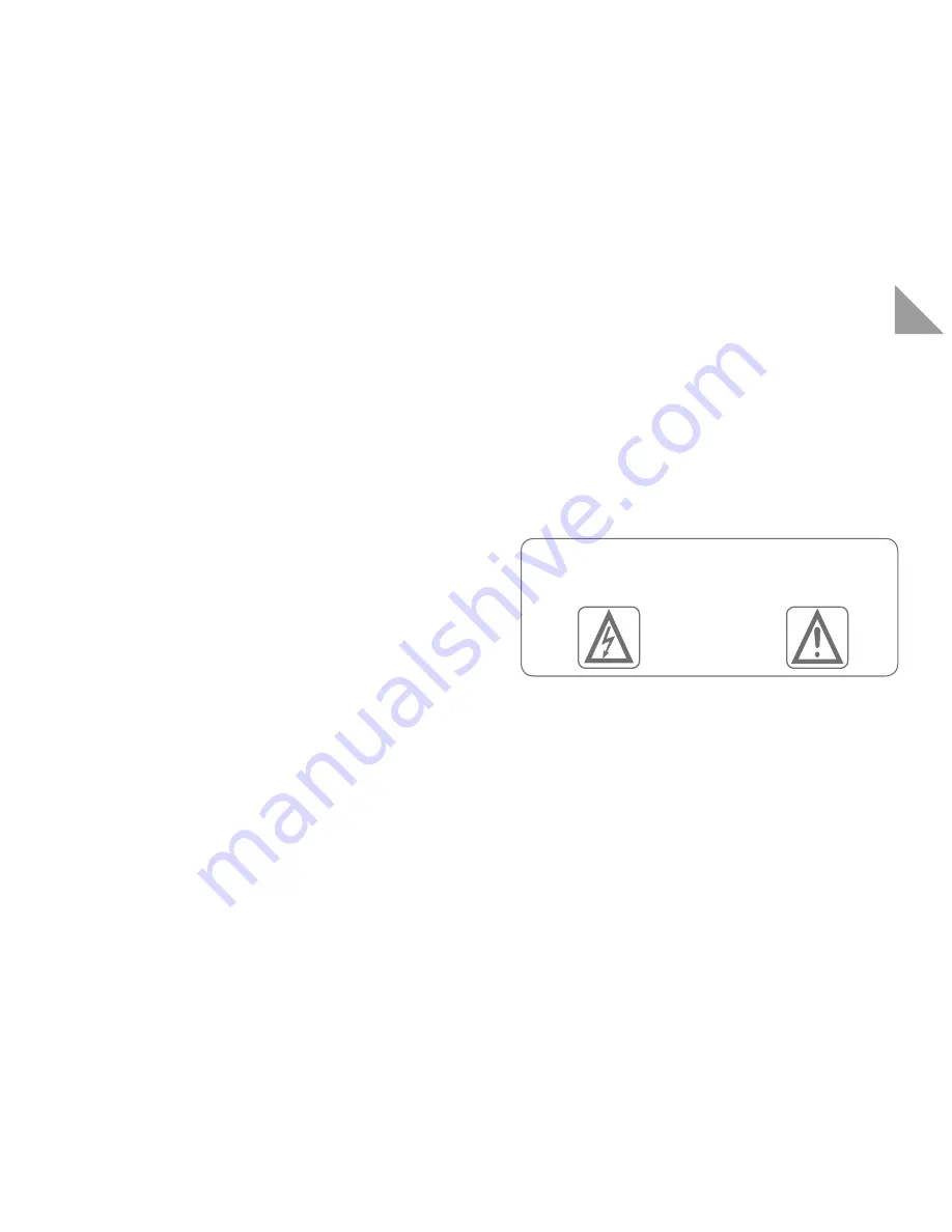
The lightening symbol inside an equal-sided 

triangle is used to warn you about the pres-

ence of non-insulated components carrying 

a dangerous, live voltage that might cause 

severe personal injuries.

The exclamation mark inside an equal-sided 

triangle indicates that there is important 

information available regarding the use and 

maintenance of your equipment.

Summary of Contents for AURUM C8

Page 1: ...AURUM C8 U S E R I N S T R U C T I O N S B E D I E N U N G S A N L E I T U N G N O T I C E D U T I L I S A T I O N M A N U A L D E I N S T R U C C I O N E S...

Page 2: ...steps listed here for installing the equipment You must abide by all of the warnings and safety instructions that are stipulated on the unit and in this instruction manual Keep this manual close to ha...

Page 3: ...down 8 Play button Press once to start the playback Repeated pressing launches the pause function 9 Stop button Stops the playback 10 On Off switch Press this button to switch the C8 on Press this but...

Page 4: ...T 250 mA L 250 V 230 V T 125 mA L 250 V 110 120 V 50 60Hz 220 240 V 50 60Hz 17W max Power Consumption Analog OUT DO NOT REMOVE COVER NO USER SERVICEABLE PARTS INSIDE REFER SERVICING TO QUALIFIED PERS...

Page 5: ...ce the range A direct line of sight connection between the transmitter and the receiver is needed Notes about the removal and the correct environmentally friendly disposal of old batteries The symbol...

Page 6: ...Sie diese Anleitung so dass Sie bei sp teren Fragen schnell zur Hand ist Das Netzkabel und andere Anschlusskabel m ssen so verlegt werden dass keine Quetschung oder Besch digung durch M bel oder durch...

Page 7: ...von Kindern fern da hier bei unsachgem en Umgang ein Erstickungsrisiko besteht BEDIENELEMENTE AN DER GER TEVORDERSEITE 1 CD Laufwerk 2 Betriebsanzeige Diese Anzeige leuchtet blau wenn sich das Ger t i...

Page 8: ...Fuse 115 V T 250 mA L 250 V 230 V T 125 mA L 250 V 110 120 V 50 60Hz 220 240 V 50 60Hz 17W max Power Consumption Analog OUT DO NOT REMOVE COVER NO USER SERVICEABLE PARTS INSIDE REFER SERVICING TO QUAL...

Page 9: ...ie Schrauben auf der Fernbedienungsunterseite und heben Sie den Deckel ab 2 Entfernen Sie die Batterie durch einfaches schieben aus ihrer Halterung 3 Achten Sie bei dem Erneuern der Batterie auf die P...

Page 10: ...t l humidit peut entra ner un court circuit de l iso lation lectrique et constituer ainsi un risque l tal Placez cet appareil l abri des claboussures Evitez de d poser des r cipients contenant des liq...

Page 11: ...le tout instant de mettre l appareil en fonction par le biais de la t l commande ou par action sur la touche 10 3 Affichage C est cet endroit que s affichent les informations d tat et les messages ce...

Page 12: ...SPDIF Digital OUT ON OFF Fuse 115 V T 250 mA L 250 V 230 V T 125 mA L 250 V 110 120 V 50 60Hz 220 240 V 50 60Hz 17W max Power Consumption Analog OUT DO NOT REMOVE COVER NO USER SERVICEABLE PARTS INSI...

Page 13: ...vant dans la t l commande par une pile neuve 1 D vissez les vis se trouvant sur le dessous de la t l commande et soulevez le capot 2 Extrayez la pile en la faisant simplement glisser hors de son suppo...

Page 14: ...cables de conexi n deben tenderse de forma que no sean aplas tados ni da ados por muebles o al pisarlos y que se eviten tropiezos Desenchufe el aparato cuando haya una tormenta o no vaya a utilizarlo...

Page 15: ...z de este indicador es azul cuando el aparato se encuentra en modo de espera se alando que el aparato puede encenderse en cualquier momento con el mando a distancia o con la tecla 10 3 Pantalla Aqu se...

Page 16: ...use 115 V T 250 mA L 250 V 230 V T 125 mA L 250 V 110 120 V 50 60Hz 220 240 V 50 60Hz 17W max Power Consumption Analog OUT DO NOT REMOVE COVER NO USER SERVICEABLE PARTS INSIDE REFER SERVICING TO QUALI...

Page 17: ...su compartimento desliz ndola 3 Aseg rese de que la polaridad de la pila nueva es la correcta El lado marcado con el signo positivo debe estar arriba junto al contacto se alado tambi n con 4 Coloque l...

Page 18: ...a digital Cinch SPDIF Tensi n de salida 0 5 Vss Impedancia de salida 300 Ohm Conexi n de alimentaci n 115 V 230 V conmutable Consumo de potencia en modo normal 12W Consumo de potencia en modo standby...

Page 19: ...ral GmbH Co KG Am Herrenh user Bahnhof 26 28 30419 Hannover Germany Telefon 49 0 511 79 04 0 E Mail info quadral com www quadral com www facebook com quadralhifi www youtube com quadralhifi Art Nr 894...

Reviews: