


1657 RLC Digibridge®
Instruction Manual
Foun 1657-0120-07/B1
®QuadTech, Inc., 1992
5 Clock Tower Place, 210 East
Maynard, Massachusetts, U.S.A. 01754
January, 1997
Tel. 978-461-2100
800-253-1230 (Sales)
800-253-1230 (Service)
Fax. 978-461-4295
The material in this manual is for informational purposes only and is subject to change, without notice.
QuadTech assumes no responsibility for any error or for consequential damages that may result from the
misinterpretation of any procedures in this publication.
Contents
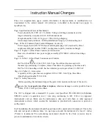
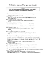
Instruction Manual Changes
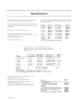
Specifications
Warranty
Introduction -Section 1
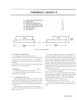
Installation -Section 2
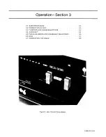
Operation -Section 3
Theory -Section 4
Service and Maintenance -Section 5
Parts Lists and Diagrams -Section 6
~ Product will be marked with this symbol (ISO#3684) when it is necessary for the user to refer
to the instruction manual in order to prevent injury or equipment damage.
Summary of Contents for 1657 RLC Digibridge
Page 6: ...Table of Contents...
Page 8: ...1 2 INTRODUCTION...
Page 9: ...INTRODUCTION 1 3...
Page 10: ...1 4 INTRODUCTION...
Page 15: ...OPERATION 3 1...
Page 24: ...4 2 THEORY...
Page 30: ...5 4 SERVICE...
Page 42: ...5 16 SERVICE...
Page 46: ......
Page 49: ......
Page 50: ......
Page 51: ......
Page 52: ......
Page 53: ......
Page 54: ......
Page 55: ......
Page 56: ......
Page 57: ......


