


5.5.2 Resistance Measurement Accuracy.
a. Set the line voltage switch, connect the power
cord, and depress the POWER button. Allow 5 minutes for warm-up
(during which time steps b through f can be done) before accuracy
determination.
b. Press the PARALLEL/SERIES button, if necessary,
so that the SERIES light stays lit.
c. Press the FUNCTION button R.
d. Press the FREQUENCY button, if necessary, so that
the 120 Hz (100 Hz) light stays lit.
e. Press the RANGE 1 button.
f. Connect the 1-
Ω
standard resistor to the test
fixture, using the extender cable, as described in para 3.1. Connect cable
I+ and I- to the posts on the front of the resistor, and P+ and P- to the
corresponding plugs on the back. (Leave G of the cable unconnected.)
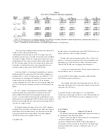
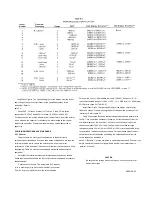
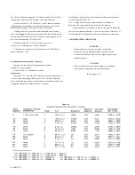
g. Verify that the R LC readout is between the min and max extremes
tabulated for check A in Table 5-4. (Refer to para 5.5.1 for exceptions.)
n. Continue through the checks specified in the table. Connect to the
decade resistor (checks D, E, etc.) as follows: stack cable tips I+ on P+ and
plug them into resistor terminal H; stack I- on P- and plug them into L;
connect G to G.
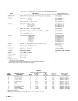
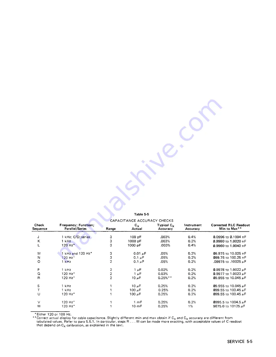
5.5.3 Capacitance Measurement Accuracy.
Continue as in the resistance accuracy procedure, above,
except as follows:
a. Follow Table 5-5 for details of setup and
performance.
b. Refer to para 3.7, for details of connection to
3-terminal capacitors with coaxial connectors and for the
determ ination of cable capacitance. The corrected readout of capacitance
is the actual display minus the cable capacitance.
CAUTION
Do NOT connect the 1417 capacitor without a
dc blocking capacitor in series with the connection between the
CURRENT H terminal and the Digibridge (I+ terminal).
c. For C standards greater than 1 uF (checks R,
S, T.. .), using the GR 1417 Four-Terminal C Standard, connect a 500-
J1F dc blocking capacitor between the CURRENT H terminal and the I+
tip of the extender cable from the Digibridge. (Orient the blocking
capacitor: + to the cable.)
d. For C standards greater than 1 uF, Cx accuracy better than that
indicated in the table can be realized by a calibration of the 1-uF value
and proportional correction of the higher values of the GR 1417. Typical
accuracy is 0.06% if the GR 1413 is used as the standard. (Refer to the
1417 instruction manual for details.) However, for
a Cx accuracy of about 0.25%, no calibration is required.
5.5.4 D Measurement Accuracy.
Continue with the accuracy procedure as follows:
a. For DUT, make a series connection of the Rand C
decade boxes, by connection from the high (H) terminal of the
resistance box to the inner low (L) terminal of the capacitance box.
Stack cable tips I+ and P+ and connect these to the inner high (H)
terminal of the capacitance
box. Similarly stack I- and P- on low (L) of the resistance
Summary of Contents for 1657 RLC Digibridge
Page 6: ...Table of Contents...
Page 8: ...1 2 INTRODUCTION...
Page 9: ...INTRODUCTION 1 3...
Page 10: ...1 4 INTRODUCTION...
Page 15: ...OPERATION 3 1...
Page 24: ...4 2 THEORY...
Page 30: ...5 4 SERVICE...
Page 42: ...5 16 SERVICE...
Page 46: ......
Page 49: ......
Page 50: ......
Page 51: ......
Page 52: ......
Page 53: ......
Page 54: ......
Page 55: ......
Page 56: ......
Page 57: ......


