


Screw K must contact etched-circuit ground. A washer is supplied
(under screw head) if necessary to do so.
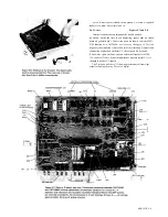
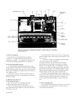
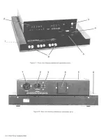
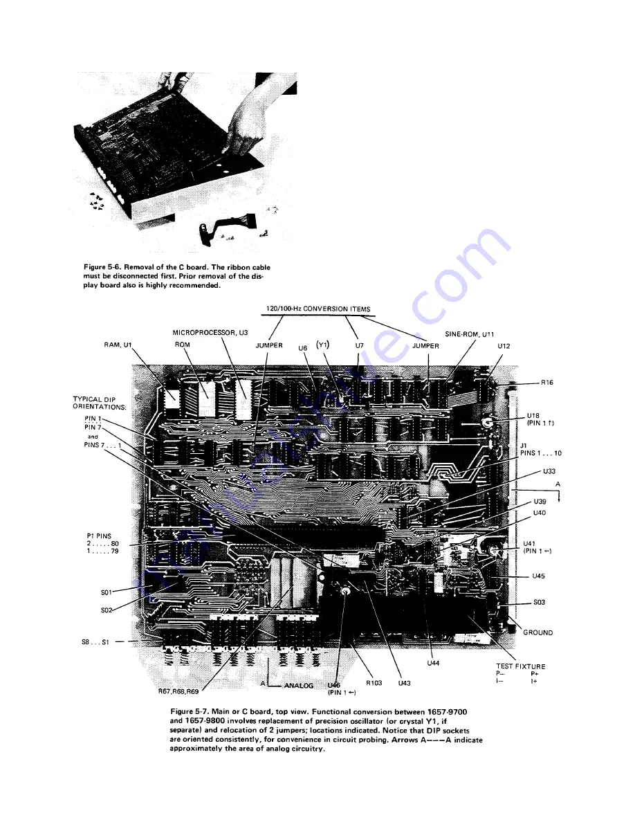
5.6.2 Access. Figures 5-7 and 5-8.
Interior locations that are important for trouble analysis
are shown. Notice the clues to pin numbering; square pads on etched
board are generally pin 1. Conversion items are shown, to make a 1657-
9700 function as a 1657-9800, or vice versa. (See para 3.1 for line-
frequency consideration.) Conversion involves relocating 2 jumpers and
substitution of precision oscillator U7; refer to parts list, Section 6.
(Thus, with a spare oscillator, one can obtain test frequencies of 100,
120, 1000 Hz.) Notice: if your instrument has separate crystal Yl, it is
changed instead of U7; inquire.
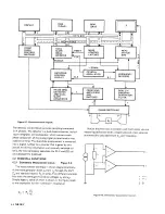
The 2 arrows with letters "A" show approximate area (front right
corner) of analog circuitry. The rest is digital.
SERVICE 5-9
Summary of Contents for 1657 RLC Digibridge
Page 6: ...Table of Contents...
Page 8: ...1 2 INTRODUCTION...
Page 9: ...INTRODUCTION 1 3...
Page 10: ...1 4 INTRODUCTION...
Page 15: ...OPERATION 3 1...
Page 24: ...4 2 THEORY...
Page 30: ...5 4 SERVICE...
Page 42: ...5 16 SERVICE...
Page 46: ......
Page 49: ......
Page 50: ......
Page 51: ......
Page 52: ......
Page 53: ......
Page 54: ......
Page 55: ......
Page 56: ......
Page 57: ......


