22
www.qualitrolcorp.com
RTD Input Wiring Connections
If you are upgrading an existing Qualitrol device, or if the RTD you have installed is a four-
wire RTD, DO NOT connect the fourth wire in parallel with the third wire, this will adversely
affect the compensation scheme.
If you have a fourth wire on the RTD connection, cut the fourth wire flush with the jacket.
Qualitrol recommends a maximum length of 75 feet for RTD cabling.
Note:
Due to dimensional and mounting variations, the RTD, well, and connector must be
ordered separately and are available from Qualitrol.
CT Input Module
For each CT Input Module, one standard clamp on the CT, TRA-017-X, is required to
calculate winding temperature or currents. Input the current range as specified.
Pull the supplied Qualitrol clamp on CT Sensor apart and place the wire which carries the
current to be sensed, into the CT opening. Push the CT sensor back together and check that
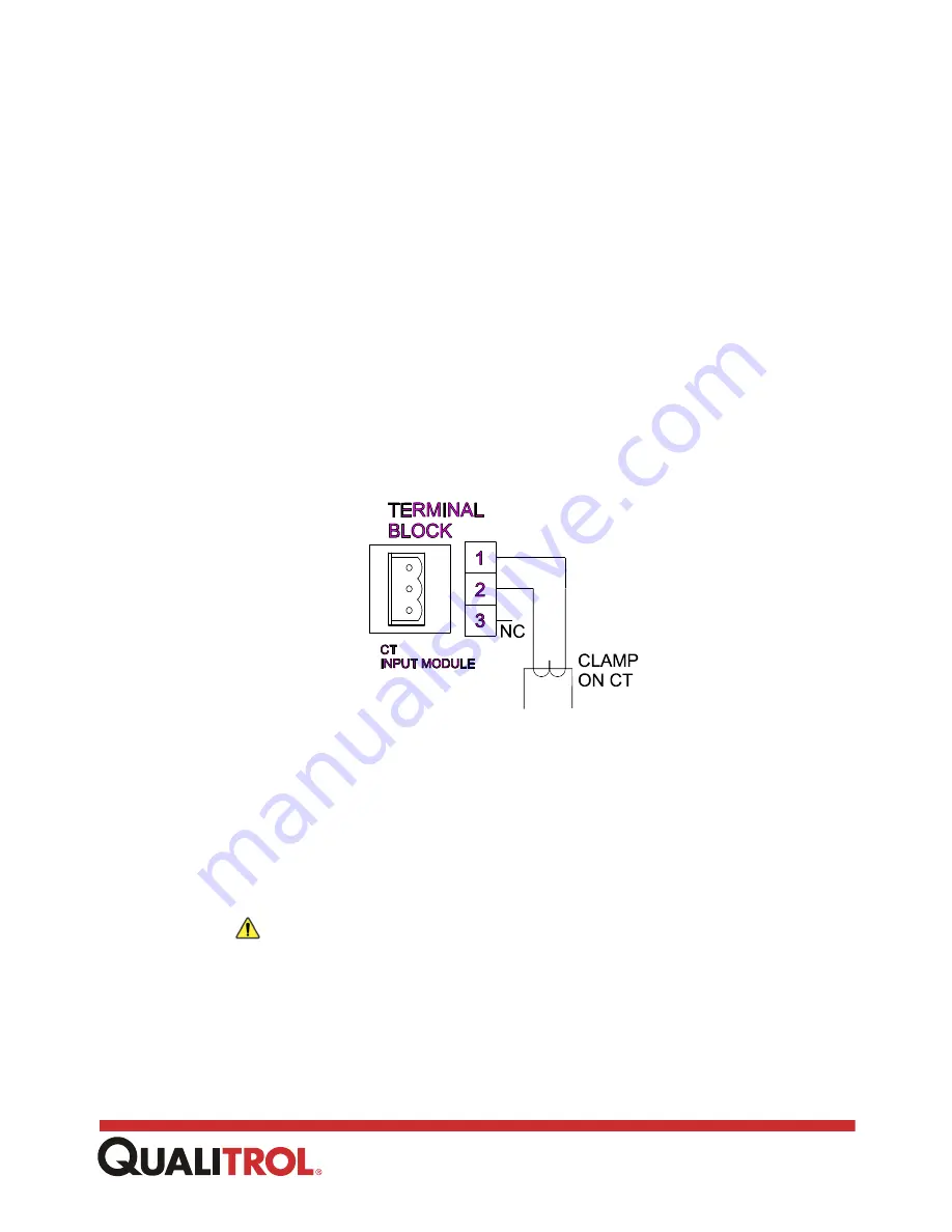
it is fully engaged. As shown in the CT Input Connections figure, connect the output wires of
the clamp on CT to the terminal board.
CT Input Connections
The Qualitrol clamp-on CT sensor comes with 20 feet of cable. While it is not recommended
to run the wire longer than 20 feet, if the application requires a longer distance, splice the
longer cable as close to the clamp on sensor as possible. This replacement cabling should
consist of shielded twisted pair wire.
Note:
Because the CT sensor is isolated from the transformer, the burden is so small it can
only be measured in a laboratory. For all practical purposes, the burden sensed by
the transformer is zero.
Caution:
The 509ITM measures current using the clamp on CT sensors. Wiring
current directly to the 509ITM will damage the unit.
AC Voltage Input Module
For each AC Voltage Input Module, one AC Voltage Sensor, TRA-600-1, is required to
measure the AC voltage. The module can measure either 0 - 140 VAC or 0 - 320 VAC,
Summary of Contents for 509ITM Series
Page 26: ...26 www qualitrolcorp com Current Input Wiring...
Page 55: ...55 www qualitrolcorp com 3 Continue with the setup procedure...
Page 101: ...101 www qualitrolcorp com...
Page 144: ...144 www qualitrolcorp com The following window will appear...
Page 167: ...167 www qualitrolcorp com The Customer Setup window displays 4 Click Load Tap Changer...
Page 178: ...178 www qualitrolcorp com Appendix...
Page 179: ......
Page 180: ......
Page 181: ......


